Aurora, Elgin & Chicago Railway uses Ohio Brass third rail insulators
|
[Trade Journal] Publication: Western Electrician Chicago, IL, United States |
||||||||||||||||||||||||||||||||||||||||||||||||||||||||||||||||||||||||||
|
Electrical Features of the Aurora, Elgin and Chicago Railway.
BY HOWARD BROOKS.
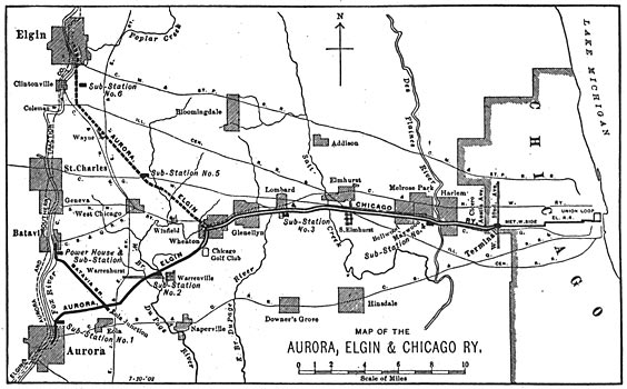
An electric railway built entirely upon private right-of-way, with easy grades and curves, steel and concrete bridges, strong and durable as the best steam railways demand, is something the electrical man has been looking forward to for years past, and to be asked for a maximum speed of 70 miles per hour would seem to be the height of ambition. However, this is no longer dreamed of, but is the matter-of-fact, every-day performance on the Aurora, Elgin and Chicago railroad. The road will have, when completed, about 80 miles of main line, of which 21 miles are double track. The distance from Chicago (Fifty-second Avenue and Harrison Street) to Aurora is 33.3 miles, and the line from Wheaton to Elgin is 16.5 miles. This part of the line is unfinished. A branch running, from the Aurora line to Batavia is six miles long. The railway serves a population of about 80,000 outside of Chicago. The same interests own the Elgin, Aurora and Southern Traction Company, with 70 miles of track; 37 miles of this line connects Carpentersville, Elgin, Batavia, Aurora and Yorkville. The remainder consists of street lines in Aurora and Elgin.
The width of the right-of-way is mainly 60 and 100 feet. On the single-track portions of the line the cuts are excavated to a width sufficient for a double track. The maximum grade is 1.8 per cent. for a mile in length, entering Aurora and Batavia, but on the rest of the system the aim has been to limit all grades to one per cent. The ordinary curves connecting tangents are of 10° and 20°, and the maximum on high-speed portions of the line is 40°. The width of the roadbed is 16 feet for single track and 28 feet for double track. The track is laid with 80-pound rails of the A. S. C. E. section, 60 feet long. They are laid with staggered joints and spliced with angle bars held by four one-inch bolts. On double tracks the tracks are 13 feet center to center, and are connected by cross-overs at intervals of three or four miles. The ties are spaced two feet center to center, with nine inches of gravel ballast underneath. The switches are all of the standard steam-road pattern.
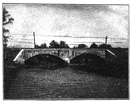
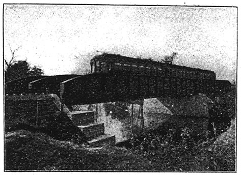
All highway grade crossings are planked and fitted with cattle-guards of vitrified-clay blocks. There are three street-railway crossings and only four steam-railroad grade crossings. Three railroad crossings are protected by interlocking plants. There are three steel plate-girder bridges, carrying the line over steam railroads and 12 bridges carry the line over streets and roads. There are, also, four bridges carrying highways over the line. All piers and abutments are of concrete. There are four arch bridges and a number of culverts and cattle-passes of like material. The Chicago terminal is a transfer station for connections with the Garfield Park line of the Metropolitan West Side Elevated Railway. The cars run between two platforms, on the outside of which is the terminal loop of the elevated railway, which is reached by an incline from the elevated at Forty-eighth Street. At Elgin and Batavia the line runs on its own right-of-way up the river bank to a terminal station in the center of the town. At Aurora the cars run for about one-half mile along Broadway Street. Through the country open platforms at road crossings serve as stopping places. Three of the six sub-station buildings have waiting rooms and platforms for passengers.
A half-hourly service is maintained in both directions. At present the time allowed for the run between Aurora and Chicago, or Elgin and Chicago is one hour 15 minutes, but this will be reduced in the future. A car recently made the trip from Aurora to Chicago (33.3 miles) in 38 minutes, making six stops. Of course, an acceleration at the rate of two miles per hour per second may have something to do with this performance. The traffic is handled by the telephone train-dispatching system, the head dispatcher being located at Wheaton. The main repair shops and car shed are being built at Wheaton, and are of fireproof construction throughout. The machine shop is spanned by an electric traveling crane, and is equipped with a boring mill, a wheel press, and all other tools found has been bent downward, in a first-class repair shop. The pit tracks have a pit two feet deep outside the track rail, to permit getting at the outside of the trucks more easily, and enables one to work at the third-rail shoes, journal boxes, etc., at a proper height for ease and comfort.
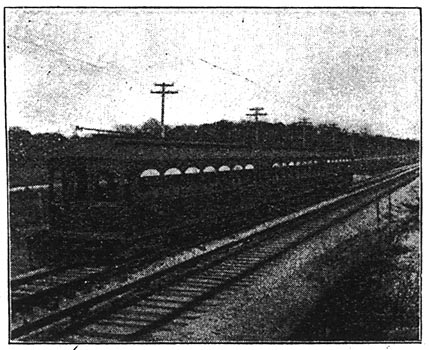
MOTOR-CAR EQUIPMENT.
The equipment of the motor cars consists of 125-horsepower, G. E.-66 motors. The General Electric Company's type-M train-controlled system with small master controller on each platform, operating magnetic "contractors" under each motor car, is used. One and two-car trains will have every axle motor-driven. Three-car trains will have one car without motor. The cars upon which these motors are placed were built by the Niles Car and Manufacturing Company. The cars are 47 feet six inches over bumpers and 39 feet four inches over bodies. This length was selected to allow the cars to pass around the sharp curves of the Union Loop in Chicago. The cars seat 56 people. There is no waste room either on the platforms or inside the car. The heating is by Consolidated electric heaters, placed along the side of the car. Van Dorn draw-bars are used, thus permitting coupling with the Metropolitan cars. The trucks are Peckham's M. C. B. 30, which follow the general lines of a M. C. B. truck, but have diamond frames and combined spiral springs and elliptic springs under the bolsters. In addition to the regular equalizer springs, which support the frame, there are spiral springs between the frame and each journal box which take a small part of the weight and are intended to prevent the tilting of the frame. Compressed-air track sanders are mounted on the truck. The Christensen straight air brakes with independent motor-driven compressor and automatic motor regulator are employed. The car wheels are 36 inches in diameter, and have a standard M. C, B. tread and flange. The axles are 6 1/2 inches in diameter. The weight of these cars is 74,325 pounds. The motors alone weigh 17,120. The gear ratio is 1.61 to 1. Owing to shortage of cars, many of them make over 500 miles per day.
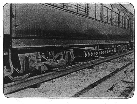
THIRD-RAIL DETAILS.
The third-rail insulators were furnished by the Ohio Brass Company. The first of these were wooden blocks set on a cast-iron base, the top of the block having a cast cap with lugs projecting upward to hold the rail in line. In using an insulator with wood in its construction, ashes must not be used for ballast, as on one of our sidetracks the wood part of the insulators burned up during a recent rain and dropped the rail on the ties. This burning was due to the acid from the cinders, although the wood blocks were boiled in paraffin and practically new. We also have had trouble in other places on the main line where much sand was in the gravel ballast. The sand splashes up on the wood and starts a leak which ends with the destruction of the insulator. The remainder of the insulators are a special design of Mr. Gonzenbach, made by the same company. This new design of third-rail insulator consists of a cast-iron base, over which fits a thin cap of Dirigo insulating material. On top of this is placed the cast-iron cap, upon which rests the third rail. The insulating material is not joined to the cast-iron fittings in any way, and the rail simply rests on the top of the cap, as the weight of the rail is sufficient to hold the three parts of the insulator together. It will be noted that the insulating portion of the Gonzenbach type is at the top. This removes the insulating material from the ground so far that the splash of rain does not reach it, so that if only a common insulating medium was used it would be very much better than any wood-block type that could be devised. It will be noted that instead of omitting the third rail at the beginning of a cross-over, to prevent catching of the contact shoes on cars which are passing through the cross-over, where the shoe comes in line with the main track, the third rail has been bent downward, so as to clear the contact shoes. This does away with underground connections, which would otherwise be necessary. For connecting across road crossings and other interruptions in the third rail, a lead-covered cable, 1,500,000 circular mils cross-section on the main line and 1,000,000 circular mils on the Batavia branch, is placed in the ground, a board being used for the protection of the cable. A cast-iron tip is put on the third rail where it is interrupted, which furnishes an incline for the contact shoe of the car. These tips are 28 inches long, and in addition to the incline they afford, the third rail is dropped 1 1/2 inches in 33 feet approaching the tip. Ordinarily the third-rail shoes come in contact with the third rail on the incline of the rail and not on the cast-iron tip, the tip being used to keep the shoes from catching the end of rail in event of their getting too low or out of adjustment. At full speed the shoes are torn off if the rail is three-eigths of an inch too high, i. e., if shoes are three-eighths of an inch lower than the top of the cast-iron tip the blow tears off the shoe. The bonding of the track rails is accomplished with two United States bonds, American Steel and Wire Company's make, at each joint. These bonds are 12 inches long with one-inch terminals and have each a cross-section of 300,000 circular mils. Each third-rail joint is bonded with two Protective Rail Bond Company's bonds of 500,000 circular mils. Tracks are cross-bonded 10 times every mile with bonds of 300,000 circular mils. It is very necessary to protect the ends of the conductor and lead covering of the cable, which is used for connecting across the break in the third rail at highway crossings and special work. If this is not done, moisture soon works in between the lead covering of the cable and the conductor. This trouble has been overcome by a special terminal designed by Mr. Gonzenbach, which serves the double purpose of forming a connector and protecting the cable insulation at the end of the cable. Electrical connection to the third rail is made by three flexible bonds, 24 inches long, soldered into the cap of the Gonzenbach terminal and bonded to the rail by a hydraulic compressor, a cap screw being used to attach this cap or top to the main part of the cable, so that it may be detached in a few seconds. The third rail between any two sub-stations constitutes a continuous section fed by the sub-stations at each end. On the line, all the third-rail sections on the entire system are connected together, through the medium of the sub-station bus-bars and feeder panels, so that there is opportunity for the sub-stations to divide the load among each other as far as the conductivity of the third rail will permit, and in case of an excessive load upon one section the sub-station nearest is not required to carry the whole load. On the double-track part of the road the third rails on the two parallel tracks are not connected together, but form two separate sections, through the medium of the sub-station feeder panels and bus-bars, just as are any other sections, but we contemplate "tying the two third rails together through a circuit-breaker located half way between the sub-stations, so that we will have the benefit of the two conductors in case of a blockade on one track. The use of a circuit-breaker would be necessary to avoid trouble on both third rails, as would happen in event of a short-circuit on one. We are trying to devise some means of overcoming the breaks in the third rail at road crossings, and are trying an overhead bow trolley at these points, but it seems as though the long contact shoe underneath the car if so arranged as to make contact with magnetic contact plates or buttons similar to the Baltimore and Ohio Railway tunnel locomotives of Baltimore, will be the most promising manner of overcoming this difficulty. The main objection to the overhead trolley is that it disfigures the right-of-way with so many poles, etc. So far as power on the car is concerned, there is no need of current at these points, as the car will coast a mile on level track, but owing to air-brake rigging and controller parts under the cars, there is not much room for an independent source of light in the cars, such as storage batteries or acetylene-gas tanks.
TRANSMISSION AND DISTRIBUTION.
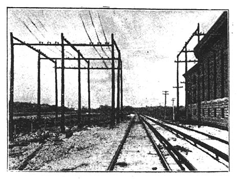
The road is laid out for six sub-stations. The transmission is by 26,000-volt, three-phase alternating current. The high-tension lines are carried on cross-arms, with insulators 30 inches between centers on the cross-arms, and the cross-arms are 24 inches apart. The telephone lines are on cross-arms seven feet below the lower transmission cross-arms. There are two telephone circuits, one for general business and the other for dispatching. The telephone lines are transposed every fourth pole and the high-tension lines every mile. The telephone wires are transposed by tying both to a single wide petticoat transposition insulator every fourth pole. The erection of 650 30-foot, 4,250 40-foot, and 150 50-foot poles under the conditions we had to contend with was not an easy task. The greater part of the poles were hauled from the nearest railway stations by wagon, and as the right-of-way was minus bridges and only partially graded, three or four 40-foot poles made a big load for one team.
The holes for 40-foot poles were put down six feet, and many were blasted with dynamite, a two-inch hole being bored six feet deep and a stick of 40 per cent. Aetna tamped in the bottom. Then the hole would be half filled and another stick put on top of this and tamped, both being, set off with a magneto generator. This made the hole the same diameter all the way up, and as the sod is cut the size of the hole intended, there was no tearing up of ground. No direct-current overhead feeders are needed, as the third rail has sufficient capacity to conduct all the current from the sub-stations to the trains. The overhead pole line has only to carry two telephone circuits, and the 26,000-volt, three-phase, high-tension feeders which supply the sub-stations. The high-tension feeders are of standard aluminum cable equivalent to No. 00 and No. 2 copper wire. The poles carrying these lines are 40 feet long, placed 80 feet apart. The system of high-tension distribution is arranged to secure freedom from interruptions of service due to short-circuits or breakages on any one transmission line. Three high-tension feeder lines leave the power house at Batavia. A line of No. 00 runs directly across the country to sub-station No. 1, near Aurora. Another high-tension pole line with No. 0000 follows the line of railroad, supplying sub-stations Nos. 2 and 3, and extending to Maywood. The line from No. 3 to 4 is No. 00. The third line, of No. 0000, from the power house is built directly across the country to sub-station No. 5 on the Elgin branch, and along the right-of-way from this sub-station to Wheaton, at which point it joins the pole line from the Aurora branch, and the two three-phase circuits run on the same poles to sub-station No. 3, with one circuit from there to No. 4. Sub-station No. 6 is supplied by a line of No. 00, running from sub-station No. 5
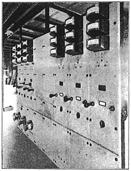
POWER STATION.
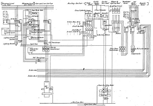
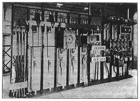
This is one of the first high-tension, alternating-current distribution plants to go into operation in which all the switching is done on the high-voltage side of step-up and step-down transformers. Each generator in the power house has its own bank of three transformers and each rotary converter in the sub-stations has its bank of three transformers. In each case the transformers are considered as a unit with the generator or converter. Each generator is connected with its bank of transformers directly without any switches or circuit-breakers. In other words, each generator and its transformers constitute practically a 26,000-volt unit. Each leg of the switch is an oil cylinder in a separate brick compartment, a motor on each switch keeping a large spring under tension, which throws the switch open or shut. After each operation of the switch the motor puts the spring under tension again. This always leaves the switch in condition to be opened or closed once, should all other power fail. The motor is operated by direct current from the exciter panel and is entirely automatic in its action. The trip of the switch is also worked by direct current from a small switch on the generator panel. It can also be worked by hand at the switch proper. Indicating lamps on the generating panel show green when the switch is open and red when closed. Taking up the circuits in their logical order, on the accompanying station wiring diagram, the main current from the generator (2,.300-volt, three-phase) is taken directly to the low-tension terminals of its three delta-connected transformers, taps being taken off between the generator and transformers for a potential transformer which supplies switchboard instruments of the generator panel. Current for all auxiliaries is taken off the generator leads between the generator and sten-up transformer. These leads are taken to the switchboard gallery through lead cable drawn through tile conduits to the transformer panel of the auxiliary switchboard, and as the present capacity of the station is four 1,500-kilowatt machines, there are four cables of three-strand conductors each, which lead to double-throw oil switches on the first left-hand or transfer panel. This panel is also fitted with a wattmeter reading the total alternating-current power required for the motor-generator exciter. The second panel contains a 2,300-volt, 110-ampere, alternating-current circuit-breaker and switch combined and also an ammeter. The third panel is fitted with a single-throw oil switch and an ammeter for each phase. This panel controls the blower motors, lighting, etc. The fourth panel is fitted with a direct-current wattmeter of 2,500 amperes at 125 volts, two triple-pole, single-throw blower-motor switches and three double-pole general lighting switches. The fifth panel is fitted with a 2,400-ampere motor-generator switch, field rheostat, voltmeter plug and 0 to 5,000 ammeter. The sixth and seventh panels are each fitted with one 1,280-ampere switch, field rheostat, voltmeter plug and o to 2,500 ammeter. These two panels are for the two steam-driven exciters, and at shutting-down time the steam exciters are thrown in parallel with the motor-generator and voltage is so adjusted as to take the load off the motor-generator. This permits shutting down without a moment's darkness in the station, or having to start any auxiliary motors that would have dropped out otherwise.
The eighth and ninth panels are each fitted with one 800-ampere, single-pole, single-throw switch, 1,500-ampere ammeter and 1,200-ampere circuit-breaker for supplying the auxiliary motors on the pumps, elevators, etc. The whole station equipment is in two halves, independent of each other, so that in event of trouble on one end of the station the other end is free. This arrangement is carried out in all steam and water piping also. The tenth panel is equipped with one field break-up switch and one field discharge switch of 250-ampere capacity for each of the four generators, and an astatic volt-meter reading to 175 volts. At first thought, it would seem that in using a motor-generator for exciting the main generators one would get extreme variations in voltage, due to the fact that load on the generators would cause a drop of voltage due to the variations of engine speed in addition to the regular drop in generator voltage due to the full or extreme overload, which in turn would cause a drop in voltage of motor-generator exciter. However, with load varying from 500 to 2,000 kilowatts on a 1,300-kilowatt machine in 80 seconds, the direct-current voltage at the sub-stations does not vary more than 10 per cent. The motor-generator is of 300-kilowatt capacity, or large enough for exciting all generators and supplying current for all auxiliary motors, lamps, etc. The main-generator current, after passing through its three step-up transformers and being raised to 26,000 volts, passes through current transformers, which are for operating the ammeter, power-factor indicator, induction wattmeter and reversal relay on the generator panel. After passing the current transformers the leads are taken to the motor-operated oil switch, from which they pass to the alternating-current, 26,000-volt bus-bars in the bus-bar compartment. The reversal relay is a combination of current and potential coils, so arranged as to trip the generator switch should current start to flow from the line toward the generators, as would be the case in event of one of the rotary converters being run as a generator from the third-rail current. Direct current from the exciter circuit is brought to the generator panel for controlling the main switches, which are located some distance from the switchboard. The generator and feeder panels have no high-tension wires upon them whatever.
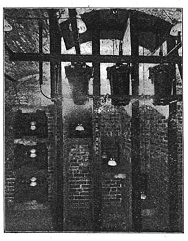
Each feeder passes first through a motor-operated oil switch, similar to those in the generator circuits. It then passes a current transformer, which operates a power-factor meter, ammeter, and the over-load relay. The relay closes the switch-tripping device, when current flowing exceeds the amount for which the relay is set. The main-feeder switches can also be operated by a hand-control switch, as well as automatically by overload. The 26,000-volt wiring in both power station and sub-stations is carried in brick flues, which isolates each circuit from adjacent circuits.
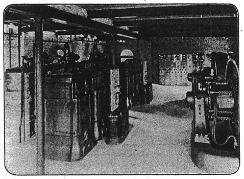
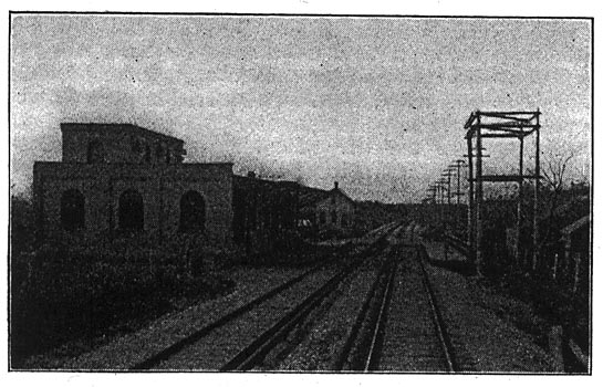
SUB-STATIONS.
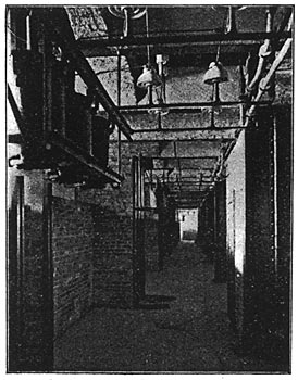
The regular sub-station equipment for all the sub-stations comprises two 1,500-kilowatt rotary converters with a bank of three transformes each. The sub-stations have air-tight bus-wire compartments, in .which air is kept under pressure by the blower for cooling the transformer and the reactive coils. The top of the coil and transformer cases have openings by which the amount of air passing may be regulated.
At the Warrenville, Lombard and Ingalton sub-stations there is another panel devoted to the out-going line to the next station. The principal object of this is to make it possible to cut off the line beyond in case of short-circuit or line trouble. After passing the lightning arresters, the incoming line goes through the current transformers which supply current for an indicating ammeter, and the current coil of a reversal relay. This reversal relay is the same as that on the power-house generator panels and will act to open the oil switch on the incoming feeder in case the sub-station attempts to give current to line instead of receiving it. After passing the current transformers the incoming line is taken to the three-pole motor-operated oil switch. The switch is also controlled 'by a hand switch on the feeder panel. From the oil switch the incoming feeder goes directly to the bus-bars. The panel for the outgoing line and controlling apparatus connected therewith are similar to the incoming, except that the motor-operated oil switch is controlled by an overload relay instead of a reversal relay, and there is an ammeter in each leg of the circuit. The potential transformer for the reversal relay on the incoming panel is connected directly to the alternating-current bus-bars. Current for the operation of the motor-operated switches is supplied by a small storage battery located in the cabinet in the sub-station.
Each rotary converter has its bank of three transformers controlled by a motor-operated oil switch. The alternating-current panel is to all intents and purposes a high-tension panel, although there are no high-tension wires upon it. After passing the main switch the high-tension lines go through current transformers for the switchboard instruments. The converter panel contains a power-factor meter, ammeter, voltmeter, overload relay and controlling switch. The machines may be started on direct current from the third rail or by alternating current, and can be started alternating current from rest and put into service in 30 seconds. When starting on alternating current the three-pole, double-throw switch located on top of the reactive coil is first thrown up, giving only half voltage until considerable speed has been attained, when this switch is thrown down and the rotary given full alternating-current pressure through the reactive coil. Since a synchronous motor produces a leading current, and as the series winding would tend to increase the leading current, the reactive coil is so wound as to balance this effect at all loads, thus keeping the power factor at unity, or, in other words, the increase of leading current due to the increase of excitation of rotaries made necessary as the output increases, is met by the increased lagging effect of the coils due to the increase of current flowing through it.
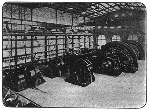
POWER-STATION EQUIPMENT.
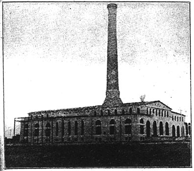
The current for operating the entire line is generated at the one power house near Batavia, Ill., on the banks of the Fox River. This will also supply current for the line from Elgin to Aurora and for the local cars in these, cities. This traffic tends to equalize the load on the station. The power house is 202 by 160 feet in size, of steel-frame construction, with brick exterior and limestone trimmings. Alfred Box & Co. of Philadelphia, Pa., furnished the 50-ton electric traveling crane. There are two cross-compound condensing Corliss engines of 2,200 horsepower, made by the C. & G. Cooper Company, Mount Vernon, Ohio. The cylinders are 32 by 64 inches, with a common stroke of 60 inches. These engines run at 75 revolutions per minute. On the shaft of each engine is mounted a revolving-field, General Electric, three-phase, 1,500-kilowatt generator and a 20-foot, 80-ton flywheel. A third engine will soon be erected and space is provided for a fourth unit. There are also two horizontal 200-horsepower engines of the Phoenix Iron Works manufacture, direct-connected to 160-kilowatt General Electric exciters. The boilers are supplied by the Edge Moor Iron Works Company of Wilmington, Del. These boilers are of the water-tube type, of 500 horsepower each and carry a pressure of 180 pounds. The chimney is of brick and stone, 240 feet high, and has an 11-foot flue. Paper read before the Chicago Electrical Association on November 21, 1902. Mr. Brooks is assistant electrical engineer of the Aurora, Elgin and Chicago Railway Company.
|