Willamette River transmission line
|
[Trade Journal] Publication: Electrical Doings New York, NY, United States |
||||||||||||||||||||||
|
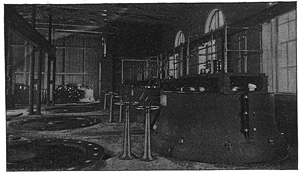
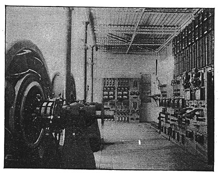
THE PORTLAND LONG DISTANCE TRANSMISSION PLANT. The work of utilizing the great water powers of the far West is progressing rapidly. Within the past year several electrical plants for the transmission of power from waterfalls over long distances have been installed, one of the most important being that at Portland, Ore. This plant was installed by the Portland General Electric Company, which owns the water power of the falls on the Willamette river at Oregon City, twelve miles above Portland, which, with a head of forty feet, has a capacity estimated at 50,000 horse-power. Part of the power has already been utilized by numerous factories and mills erected near by, and in addition to these an electric station erected some years ago has supplied current for lighting the streets and dwellings of Portland and for operating an electric street railway between Oregon City and Milwaukee, seven miles away, the direct current and high frequency alternating systems being used. The station is located on the west side of the Willamette river, opposite Oregon City, and is being put up in sections. Twenty sections will complete the building, five are already built and foundations are now being laid for the remainder. The ultimate generating capacity of the station will be 12,800 horse-power. The station building is of concrete, stone, iron and brick, and when finished will have a length parallel with the river of 364 feet. The water is taken from the canal on one side, led through an extensive hydraulic installation and discharged into the river below on the other side. The water wheel plant consists at The present time of three units, each consisting of a pair of vertical cylinder gate improved Victor turbines, from the shops of the Stillwell-Bierce Smith-Vaile Company, of Dayton, O., one wheel being forty-two inches and the other sixty inches in diameter. The larger wheel is brought into service only at periods of excessive high water which the records show occur once in every five years. The smaller wheel runs at a speed of 200 revolutions per minute, and the larger at 100 revolutions per minute; both turbines are set on the same level, and the shaft of the larger wheel carries a pulley. The upper end of the forty-two inch wheel shaft is provided with a coupling for connecting it with the shaft of the dynamo, which is mounted above it, as shown in Fig. 1. The generator shaft carries a pulley in line with that on the shaft of the larger turbine, so that the smaller turbine may be uncoupled and the generator belted to the larger of the two wheels. When the smaller turbine is operated alone the belt lies upon a shelf surrounding the pulleys.
The weight of the vertical shaft with the armature is about 33,500 pounds, and to carry this a system of extra bearings is introduced, one of the ring-thrust type and the other a hydraulic oil bearing, both supplementing the ring bearings on the armature shaft. They are enclosed in cases filled with oil delivered by hydraulic pressure, and are surrounded by water jackets. The length of the generator shaft is twenty-nine feet, and it is eight and three-eighth inches in diameter. Both wheels in each section are controlled by hand wheels and .both are regulated by the same governor. The belt tightener is also controlled from either floor by a hand wheel. Water is admitted to the penstocks from the upper canal by means of a head gate operated from a platform on the canal side of the station. Each penstock is ten feet in diameter and is constructed of rivetted steel plates. Each wheel has its own flume, the water passing first through the large flume of the larger wheel to the flume of the smaller wheel, whence it passes through a tube into the tail race. In addition to these turbines there is an additional equipment consisting of a set of pumps, including a hydraulic pump for supplying oil to the thrust bearing cylinders and a duplex water pump to circulate the water in the cylinder water jackets. They are operated by two fifteen inch horizontal turbines enclosed in the same flume. For the operation of, the exciters another pair of vertical turbine wheels has been installed. each forty-eight inches in diameter, driving the generators by a similar system to that already described for the operation of the large machines. The complete power plant will consist of twenty three-phase generators, with two direct current machines acting as exciters.
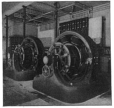
The five sections of the building already erected are occupied as follows: The first section contains the pumps and the accumulators for the complete station; in each of the other three sections is a three-phase generator of 450 kilowatts capacity, and the fifth section contains two 250 kilowatts multipolar continuous current generators used as exciters. One exciter is capable of supplying the fields of all of the twenty three-phase generators the second machine being set up as a reserve in case of accident to the first. At present one of them is furnishing current to the street-railways in Oregon City. When the station is complete the exciters will be removed from the fifth section and placed in the centre section of the building, where the switchboards will also be erected. The generators are of special design and are set upon the floor of the station, the armature revolving in a horizontal plane with one bearing at the floor line and another on top of the armature underneath the collector rings. Each generator has twenty poles. The armatures are a little over seven feet in diameter and are about two feet high. They are constructed to deliver current to the line at 6,000 volts E. M. F. without the intermediaton of step-up transformers. The exciters are also of the vertical type, so that the armatures revolve in a horizontal plane; there is one bearing only at the floor line. The construction of the exciters is almost identical with the General Electric multipolar type of railway generator, and each has a capacity of 250 kilowatts at 125 revolutions per minute.
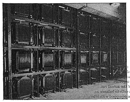
The line is 14.3 miles long, a separate circuit being provided for each machine. It passes through an undulating country following the course of the Willamette river as closely as possible. The loss in the long distance transmission line is calculated at full load at about eleven per cent. The sub-station to which the high tension lines are brought is a two-story building, covering a space of 40 feet by 100 feet. The lower floor is divided into three rooms, one containing the transformers and the second the rotary converters, the other side being used for a repair shop, lamp and meter room. In the transformer room at present are forty-five transformers, the receiving end of each line being connected to a bank of fifteen transformers, five of which are placed between each pair of wires of the three-phase system. The transformers are mounted on an iron rack five transformers high and three wide. The transformers are of the standard General Electric sub-station type, having numerous air passages between successive bunches of iron laminae and between the coils so that they may be cooled by artificial ventilation. The distribution of light from the secondaries is effected on the four wire system, which allows the working of synchronous and induction motors from the lighting mains. The four wire system is worked at 133 volts between any two wires and by means of feeder regulators a variation of seven and one-half per cent. in either direction is covered. The direct current for the railway service is obtained by means of rotary converters. Two of these are at present installed in the sub-station, and space has been left for three more. Each converter will deliver 500 horse-power to the bus bars of the continuous current switchboard.
The long distance transmission lines for this railway service, as in the case of the lighting circuits, are connected to step-down transformers, transforming the current from 6,000 volts on the line to 400 volts at the secondaries, which feed the rotary converters; the rotary converters are compounded for self-regulation and run at 500 revolutions a minute. At present, the lighting from the three-phase system is used for large buildings, containing several hundred lights each. They are close to the city station, and this distribution can be readily handled at about 400 volts. For the outlying and residential districts the high frequency apparatus with individual transformers will still be employed.
The railway current is carried to the east side railway station by means of cables under the Willamette river, and this distribution reaches as far as Milwaukee, where connection is made in parallel with the 600 volt service from either Station A or Station B at Oregon City. The loop from Oregon City to Portland and back is thus as follows: Beginning at Oregon City with thirty-three cycle three-phase current at 6,000 volts, 14.3 miles are traversed as far as Portland; the current is then transformed to 400 volts alternating and passing through a rotary converter, issues therefrom at 600 volts continuous, which is transmitted eight miles to Milwaukee and connected with the continuous current from Oregon City.
|