Pelzer, SC Transmission Line
|
[Trade Journal] Publication: Electrical World New York, NY, United States |
|||||||||||||||||||||||||||||||||||||||||
|
A Cotton Mill Electrical Transmission Plant. BY A. F. MCKISSICK.
TOWARD the middle of the year 1894 the Pelzer Manufacturing Co., of Pelzer, S. C., decided to increase its plant by the addition of a new mill (No. 4), and to develop for the use of this mill a water power owned by the company, located about two miles farther down the river on which Mills Nos. 1, 2 and 3 are located. After considering the many advantages offered by electrical transmission, it was decided to adopt that system, and the following October the contract for the entire electric equipment was awarded to the General Electric Company. This equipment consists of three 1000-hp generators (three-phase), of 3300 volts each, all station apparatus, a line 2-5/8 miles in length, 21 induction motors of various sizes, all necessary transformers, switches, lightning arresters, 1200 incandescent lamps for lighting the new mill, two 5-hp pump motors and one 400-hp synchronous motor for operating Mill No. 3, replacing therewith a 400-hp Harris-Corliss engine.
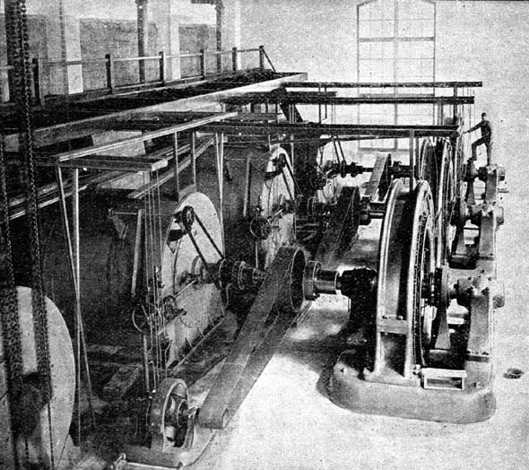
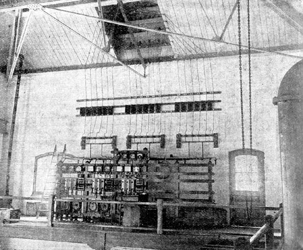
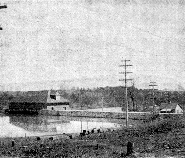
The work of installation of this plant is at this date very nearly completed. Some of the motors have been in operation since Dec. 22, 1895, and at this date about half the motors are being used continuously at the new mill. Beginning the description of the plant at the dam, the initial cut gives a very good view of the same, with the power-house on the left. This dam is built of solid masonry, has a 34-foot fall and a capacity of 5500 horse-power. Fig. 1 shows an interior view of the power-house, which is constructed of brick and stone. At present there are installed three 1000-hp three-phase generators of 3300 volts, direct coupled to Victor horizontal turbines, revolving at a speed of 167 revolutions per minute. The casings and all necessary tubings for two more turbines have been installed, with a view to increasing the capacity of the plant in the future to the total capacity of the water power. Figs. 2, 3 and 4 show the plans and elevations of the power-house. Fig. 5 gives a view of the switchboard, which is located in the gallery. The three generators are connected to the bus-bars on the switchboard, from which are led direct without the intervention of transformers the line wires, consisting of 18 No. 00 bare copper conductors. Carpenter enamel rheostats and Weston measuring instruments are used on this board.
A view of the line is shown in Fig. 6, which was taken just above the power-house. The poles are all of cedar, 40 feet high, well pointed at the top. On the upper cross-arm are strung two "buckthorn" wires for the protection of the circuits from lightning. These wires are connected together and grounded about every third pole, according to the location. The length of this pole line is two and five eighth miles. On the next three cross-arms are strung the 18 copper conductors, six on each cross-arm, all of the same polarity. On the lower cross arm are strung the pressure wires and the telephone wires. A specially constructed large glass insulator is used on this pole line. At a point about three quarters of a mile from Mill No. 4 branch wires (No. 4 B. & S.) are led to the synchronous motor which operates Mill No. 3. At this point, where the wires branch to Mill No. 3, all the conductors of the same polarity are bonded together.
The conductors at the end of the line lead into a tower, of Mill No. 4, and from this tower go to the transformer room in the basement of the mill, through an underground tunnel. In this tower are located the lightning arresters, which are of the "G. E. type L, Form A." This mill is 506 feet long and 128 feet wide, four stories high, and has a floor space of seven acres, approximately. It is the largest cotton mill in the South, and is among the largest mills in the world under one roof. It has a capacity of 55,027 spindles and 1400 looms, and will manufacture a fine grade of cloth.
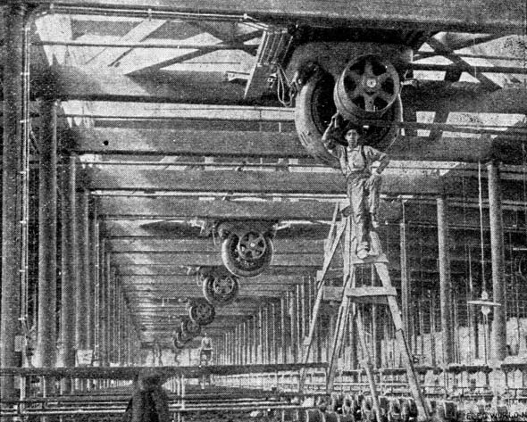
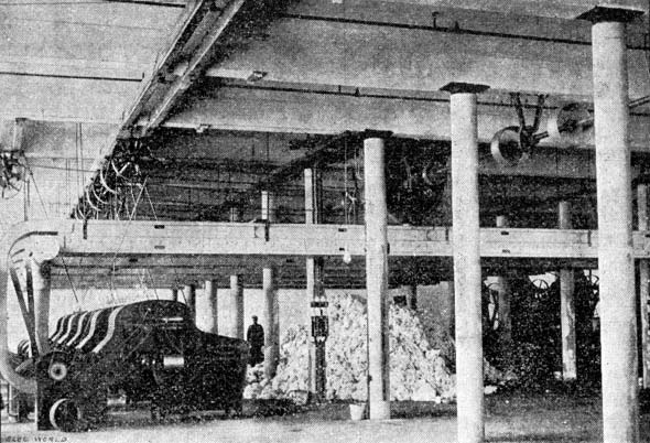
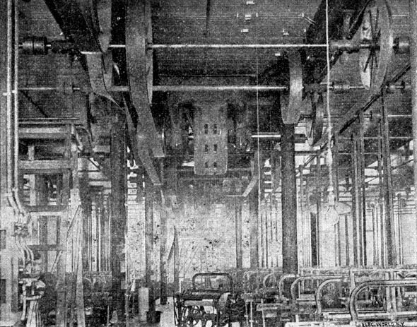
In the transformer room are located the transformers, all switches and other switchboard apparatus. The transformers are artificially cooled by an air-blast from two blowers, operated by two 5-hp motors. The motors on the different floors are supplied with current at a pressure of zoo volts, and are of the three-phase induction type, with no sliding contacts of any kind. These motors are bolted to the ceiling, thus saving much valuable floor space. In the basement there are two 50-hp motors operating the blowers, exhaust fans, repair shop, etc. The first floor is devoted to weaving and picking. In the picker room (Fig. 8) are located four 75-hp motors, direct connected to counter shafts, and in the weaving room (Fig. 9) are four 110-hp motors, operating 720 looms on this floor and 680 on the second floor, there being also on the second floor five slashers. The carding room (Fig. 7) is located on the third floor, requiring for its operation three 110-hp motors, and on the fourth story, which is the spinning room, there are eight 110-hp motors (Fig. 10). The same plant also furnishes current for 1200 incandescent lamps for lighting this mill, and current for operating two 5-hp motors for driving pumps.
The guaranteed efficiency of this plant, from the turbine shaft to the motor shaft, is 80 per cent. and the regulation of the motors is guaranteed not to exceed a variation in speed of 2 per cent. In inspecting this mill, there are three facts which appear very striking to an engineer: First, that the largest belt in this mill, where 2000 net horse-power are utilized, is only eight inches wide; second, that the pulley is only thirty inches in diameter; third, that there are in this mill over a score of independent sources of power, thus doing away with long lines of shafting and long, heavy belts. This company undoubtedly adopted the best plan when they decided to use electrical transmission. After it had been determined to build this new mill and to utilize for its operation the water power below the other mills, there were two methods of attaining this end possible, and to choose the most practical and the most economical was the problem. These methods were: First, to locate the mill near the water power and use direct belt or rope transmission and second, to use electrical transmission, placing the mill in a convenient location and one that did not require excessive excavations. If the first method had been chosen, the extra expense necessary for the excavations and foundations for this mill would have equalled two thirds of the cost of the whole electrical equipment, including the 400-hp synchronous motor for Mill No. 3 and the lighting apparatus for Mill No. 4; and when to this cost of foundations and excavations are added the cost of building and maintaining a spur from the railroad about three miles long, we can see that in point of first cost, the mill where it is now located cost practically the same as it would have cost had it been situated at the water power. By placing the mill where it is now located, the following advantages are obtained: First: Proximity to the other mills, thus saving duplication of mill offices, stores, churches, school houses and other mill village necessities. Second: The choice of the location of the mill, as in this case it is located in what is practically a level field, in close proximity to the railway and near the other mills. Third: The saving of the annual consumption of 2500 tons of coal, costing approximately $9000, by the substitution of a motor for the engine in Mill No. 3. As an example of the transmission and the proper sub division of power, the Pelzcr plant stands most certainly very high. Much credit is due for this radical departure in mill work to the officers of the company, Capt. E. A. Smyth, president and treasurer; Mr. A. L Blake, secretary, and Mr. B. F. Guy, superintendent, and to Messrs Lockwood, Green & Co., of Boston, mill engineers and architects, who designed the plant.
|