Fred Locke Victor insulator (Locke 2-spout)
|
[Trade Journal] Publication: Electrical World and Engineer New York, NY, United States |
||||||
|
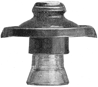
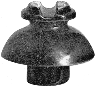
Insulators for High Potential Transmission. At a time when the development of power transmission is being carried on so rapidly, it is interesting to note the gradual evolution of the high potential insulator. In this article are illustrated two sizes of the "Victor" type of insulators manufactured by Fred M. Locke, of Victor, N. Y., who has done much to make possible the transmission of electrical energy at extremely high voltages. One cut represents a No. 304 "Victor" insulator, adapted to 40,000 volts, and another is a No. 316 "Victor" insulator for 60,000 volts. The same type includes insulation for any voltage down to 7000 volts. These insulators are made in brown or white, and every insulator is tested to twice its normal line capacity before leaving the factory, which ensures perfect insulators for erection and minimizes the possibility of breakdown after the line is placed in operation.
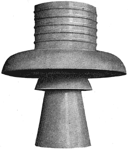
The No. 316 has been adopted by the Standard Electric Company of California and by the Bay Counties Power Company to carry 60,000 volts line pressure, the total length of line aggregation 400 miles. In connection with the transmission of the Bay Counties Power Company, a nice problem has been presented in carrying the high voltage cable across the Strait of Carquinez, a distance of about 4700 ft. To meet the excessive strain of the cable, which is 19-strand steel, 7/8-in. diameter at this point, and to give the necessary insulating qualities, there have been designed by Mr. Locke immense porcelain supporting and strain insulators. The supporting insulators are, in turn, supported by structural steel towers on both sides of the strait. An illustration of this supporting insulator is also shown here. This is 11 ins. high, 18 ins. in diameter and weighs 45 lbs. The strain insulator is 11-1/2 ins. in diameter and weighs 32 lbs., surrounding the cable for a distance of 24 ins., and will be required to withstand a strain of 12 tons. There are to be four cables placed "staggering" so that they cannot approach one another within 25 ft. This span, which is the longest on any power transmission line in the world, is truly a remarkable piece of engineering, taking into consideration its great length, the weight of the cable and the high voltage, and is characteristic of the heroic means employed in developing power resources to-day in America.
|


