New Haven Electric Railroad, Photos show U-966
|
[Trade Journal] Publication: Scientific American New York, NY, United States |
|||||||||||||||||||||||||||||||||||||||
|
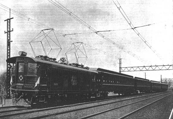
INAUGURATION OF THE NEW HAVEN RAILROAD ELECTRIC SERVICE. [See page 79.]
· · THE INAUGURATION OF THE NEW HAVEN RAILROAD ELECTRIC SERVICE.
Because of the fact that the inauguration of electric service on the New Haven system marks the first application of an alternating current system to the operation of a trunk line railroad in this country, the event will necessarily command widespread attention. It is true that the alternating current has been so used for several years in Europe, notably on the Valtellina line in Italy. In this country, also, single-phase current has been in successful operation on certain interurban lines. The New Haven Railroad equipment, however, is the first instance of the application of single-phase traction to an important trunk railroad; and the fact that, throughout the whole of the 22-mile electric zone, the road is equipped with four tracks, and carries an unusually heavy suburban and express service, gives this service an importance equal to that which attaches to the third-rail equipment of the New York Central lines, which has now been in successful operation for over six months. The electric zone of the New Haven system extends from Stamford to Woodlawn, a distance of 22 miles. From this point to the Grand Central terminal station in New York, the trains run over the tracks of the New York Central Railroad.
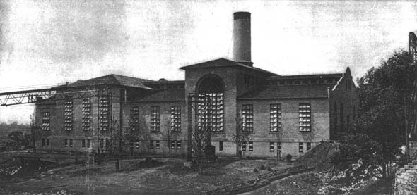
THE COS COB POWER STATION.
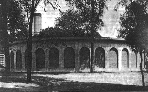
The electric zone, throughout its entire length, is served from a power station located on the water front at Cos Cob, some three and a half miles from Stamford, Conn. The site selected is a picturesque point of land, which was formerly the summer home of the celebrated tragedian Edwin Booth. The architectural treatment of the building is simple and dignified, and harmonizes well with the natural features of the site. Unlike many of the later power stations, the structure rises only one story above ground level; although there is a deep excavation below the engine and boiler rooms for the accommodation of the coal bunkers and various auxiliary machinery. The boiler house occupies the westerly portion of the building, while the easterly bay is given up entirely to the turbines and generators. The whole building is abundantly lighted, and all the windows, from top to bottom, are provided with swinging sashes, with a view to providing ample ventilation. The boiler house is equipped with sixteen Babcock & Wllcox boilers of 520 horse-power each. The coal is delivered at a wharf situated at a distance of about 400 feet from the power station. Here it is lifted from the barges and delivered to the top of a receiving tower, where, after being crushed, it is delivered to the cars of an inclined cable system, which runs from the tower to the roof of the boiler house. It is then delivered into a hopper, and taken away by a flight conveyer, either direct to the boilers or to the bunkers in the basement of the building. From the bunkers it is taken by a bucket conveyer and returned to the flight conveyer for transport to the boilers, where it is delivered direct to the Roney mechanical stokers in the furnaces.
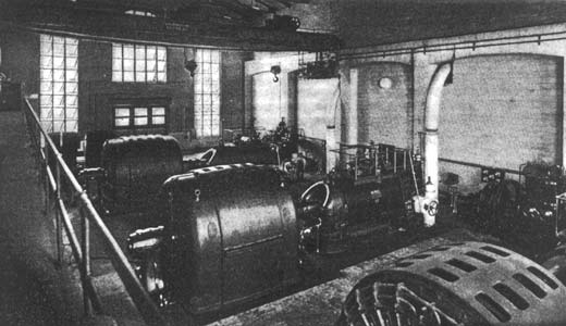
The engine room contains four 3,750-kilowatt turbo-generators of the Westinghouse-Parsons type. The turbines receive the steam at 200 pounds pressure and 100 degrees of superheat. They run at 1,500 revolutions per minute, and deliver single-phase current to the trolley system under a tension of 11,000 volts. The engine room equipment also includes two 13-inch Westinghouse compound steam exciters and one motor generator set exciter. The turbo-generators are among the latest built by the Westinghouse Company, and they are splendid specimens of the engine builder's art. In spite of the fact that the rotating parts of each set weigh 56 tons, and that the speed of revolution is 1,500 per minute, there is practically no vibration.
THE OVERHEAD TROLLEY SYSTEM.
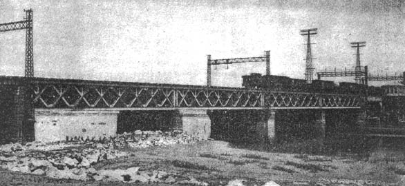
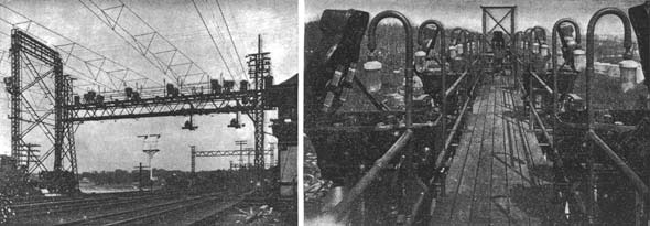
The construction of the overhead trolley line is unquestionably the most novel feature of the New Haven Railroad equipment, at least from a constructive point of view. It was realized, when designing the system, that in view of the high speed of many of the trains, which frequently reaches from 70 to 75 miles an hour, it would be necessary to provide a trolley wire which would remain in true line and level, as distinguished from the loose and swaying wires of the ordinary trolley-car service. The system is built as follows: At about every 300 feet, the tracks are spanned by heavy latticed bridges erected upon massive concrete foundations. The bridges consist of two end posts and a deep latticed truss spanning the entire width of the tracks. The wires of the transmission line and signal service are strung upon the posts, and the four catenary trolleys are hung from the trusses. Each catenary consists of two half-inch steel "messenger" cables, which are cradled in the same way as the cables of a suspension bridge, and from these, and midway between them, is suspended a 3/8-inch copper trolley wire, the attachment being made by a series of triangles, which decrease trom 6 feet on a side at the trusses to 6 inches at the center of each span. The triangles are formed of 3/8-inch glavanized pipe and they serve to hold the copper wire firmly in alignment and level. At intervals of two miles the place of the ordinary bridge is taken by a special tension bridge of much heavier construction sufficiently heavy to enable it to take up the slack of the wires when adjustment of that kind is necessary. Upon the bridges, also is carried a set of section brake switches for cutting out the two mile section of the road which they serve. One of our illustrations shows a bridge of this kind, as viewed from the entrance to the Cos Cob railroad bridge. To the left is shown a tall tower from which the feeder lines are carried across the tracks to the power station. Another view, taken from the floor of the section brake switch bridge, gives an excellent view of the switches, which are i here shown in the open position. When the switches are closed, the hinged cover serves to protect the whole mechanism from the weather.
From the foregoing description and the illustration it will readily be understood that the overhead trolley line construction is of a very costly character, and as a matter of fact, the average expenditure for this work has worked out at about fifty thousand dollars per mile.
THE ELECTRIC LOCOMOTIVES.
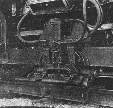
One of the chief economical advantages of the use of the alternating-current system is that it is not necessary to build, at stated intervals along the railroad, the costly sub-stations which form a necessary part of a direct-current installation. Instead, the stepping down of the current is done by transformers carried upon the locomotives. The provision of these transformers, of which there are two for each locomotive, adds greatly to the weight, which, in the case of the New Haven, reaches the high figure of 95 tons although the rated power is only 1,000 horse-power. This is about the same weight as that of the New York Central direct-current locomotives, which have a normal rating of 2,200 horse-power. An interesting feature in these machines is that they have been arranged to take either single-phase current from the overhead line, or direct current from the third rail and with a view to making our readers familiar with the internal construction, we present two sectional views with numbered references, covering the whole of the internal construction.
The locomotives are carried upon two four-wheeled trucks, and are provided with four 250-horse-power motors, one to each axle. The motors are of the compensating gearless type. They are suspended from frames, which fit over the trucks and rest upon the journal boxes, the motors being supported on four bolts provided at their lower ends with colied springs. The armature is not directly connected to the axle of the truck, but is mounted on a quill which surrounds the axle, which it clears by 5/8 of an inch. Upon this quill are mounted the bearings of the wheels. The quill is formed with a wide flange at each end, and projecting from the face of each flange is a series of stout pins, which engage a series of pockets formed in the hub of the adjoining wheel. A series of coiled springs is interposed between the pins and pockets, which serve to transmit the power from the motor to the wheels without jar. Similar springs are disposed between the ends of the pins and the bottom of the pockets. This construction provides for a certain amount of vertical and lateral movement, while the motor is centered axially by the compression of the springs between the end walls of the pockets and the flanges of the quill. In order to prevent the motors from pressing against the wheels under the action of centrifugal force on curves, they are arranged to bring up against rails mounted on the truck frames. With the exception of the driving wheel axles and journal boxes, the entire locomotive is spring-supported. Particular attention has been paid to the ventilation of the motors. To this end, the channel beams, which form part of the framework of the car, are made to serve as conduits, through which air is driven, by means of a fan in the cab, to the motors and transformers. The air current, in addition to carrying off the heat generated by resistances, also serves to keep the motor free from dust. Each locomotive has been designed of sufficient power to handle an ordinary local train of from six to eight cars at the service speed. For hauling the through express trains, two locomotives will be coupled up in tandem. It is estimated that in local service, a 300-ton train can be operated at an average speed of 26 miles per hour with stops about two miles apart, the maximum obtainable speed between stations being about 45 miles an hour.
The service was opened on Wednesday, the 24th of July, by the operation of all the local trains, twelve in number, running between New Rochelle and New York. In two weeks' time service will be extended to include the Port Chester locals, of which there will be twenty-three. Soon after that, the Stamford local service will be added; and, finally, the express service will make the change from steam to electric locomotives at Stamford; after which no more steam locomotives will enter the Grand Central Station.
|