Notes on Electrical Development and Experience in the Cripple Creek Mining District
|
[Trade Journal] Publication: Electrical World and Engineer New York, NY, United States |
||||
|
Notes on Electrical Development and Experience in the Cripple Creek Mining District, Colorado. By J. R. Cravath.
THE word district is commonly and aptly used by those familiar with this (the greatest) gold mining camp of America. The Cripple Creek District includes two large towns (Cripple Creek and Victor), six smaller towns large enough to warrant electric lighting service, a score or more of large regular dividend-paying mines, and hundreds of claims in various stages of development. Such a condition of affairs, with towns and mines close together, naturally would seem to be conducive to electric power transmission, and so it is. Coal is worth, at the mines, from $6 a ton up (principally up) at the mines on the mountain side where it is needed. Water is also scarce. There are at the present time two companies in the business of supplying electric power in the district and a third about to enter the field. Although but a comparatively small per cent of the mines are run by electric power the power houses now running are well loaded up considering the time they have been in the field. When one considers that the camp is ten years old and that for eight years mining operations have been going on upon an extensive scale, while the oldest power company has been in the field only since the summer of 1898 and the amount of electric power is comparatively limited, it is not surprising that the per cent using electric power should not be larger. It is surprising, however, that the idea should exist which does among many of the miners that they can generate their own steam power cheaper than they can buy electric power. This idea is of course based entirely on ignorance of what steam power actually costs, and will be eradicated in time. Then, too, steam plant employees have opposed any change which jeopardized their positions. However, as there is not enough electric power to go around, perhaps it is a good thing that all do not want it at once. Power rates in the district are from $0.04 to $0.02 cents per kilowatt hour approximately, as near as can be stated in a general way. The large mines, as a rule, cling to their established steam plants. The small users are, after all, the most desirable customers of the power companies, as to secure the business of large mines requires low rates, and neither of the power companies is fixed at present to handle many very large induction motors. The smaller and newer mines make the best customers, as they have no large steam plants to throw away when they adopt electric power, and the small motors they use do not cause serious fluctuations in the load.
Aside from lighting, the principal use of electricity in the Cripple Creek mines is in driving air compressors, pumps and hoists. The air compressor and pump load is, of course, a fairly steady one, and is a desirable one, from the power station standpoint, not only because of its constancy, but because a mine owner is more likely to realize how much it costs him to run his air compressor by steam than how much his steam hoisting costs him. Nevertheless, hoisting is a very important feature of the electric power business. Although there are several kinds of induction motor mine hoists in the district, one general type has by common consent been settled upon as the most suitable for the work. In this the motor is geared to the winding drum and in starting the motor resistance is introduced into the armature circuit. The motor is controlled by a street railway type of controller and levers are provided with the hoist, one of which applies a band brake to the drum, the other works a friction clutch which can disconnect the motor from the winding drum. The General Electric hoist controller, which was the first of this type, using resistance in the armature circuit, has provisions for reversing the motor and helping the bucket going down. The Westinghouse controller only operates the motor to lift the load and does not reverse, but depends on the weight of the bucket and use of the brake to effect the descent. It is found that starting these induction hoist motors by introducing resistance in the armature circuit takes much less current and affects the voltage of the supply circuit much less than the use of an auto-converter or reactance coil in the field circuit for starting, as used on some of the older hoists, and the gain in this respect fully pays for the added complication of collector rings on the armature shaft which the use of resistance in the armature circuit necessitates. There are as yet no mine locomotives in the district, as the conditions do not as yet require them; so that branch of electrical mine work is not represented. Electric drills have not been introduced yet, but as there are several good designs now on the market they will probably be used in the near future. The running of ventilating fans in mines and mills is another application of electric power, and this will probably become more important if electric drills are introduced and compressed air is not used in a mine. The plants and distribution systems of the companies now in the field are very substantially constructed with a view to permanency and reliability. They were not built until the permanency of the camp as a gold producer was well assured, and were built as a sound investment proposition. Of the three plants, one generates power 24 miles away with a steam plant, one has a steam plant in the district, but is identified closely with the railroad, which furnishes coal, and the third will use a water power 11 miles distant. THE COLORADO ELECTRIC POWER COMPANY
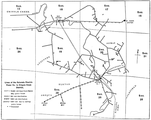
has its power house 24 miles away, at Canon City, on the Arkansas River, where coal and water are cheap. Power is transmitted from Canon City to the district over a 3-phase 20,000-volt line. There are two sub-stations in the district from which power is distributed at several voltages. The greater part of the distribution is direct from the sub-stations to the motors at 500 volts, 3-phase. There is also a 2500-volt line running out of one sub-station to some distant mines and a 6600-volt line running out of another sub-station to supply the electric railway power house. The map (page 77) of the companys distribution system in the district shows how extensive is the use of electric power in the mines. The distances can be judged from the township section lines, which are one mile apart. The 20,000-volt transmission line comes in from the south, as shown, and branches at sub-station No.1. One branch goes into sub-station No.1 and the other cuts across the hills, as straight as practicable, to sub-station No. 2. The stations are a little more than a mile and a half apart. As shown by the map, the 500-volt secondary distribution system forms a network, tied together in as many places as possible. The 500-volt secondary lines, from the two sub-stations, are run in parallel. Thus full benefit is obtained from all the transforming apparatus in both the sub-stations and from all the copper in the lines. Sub-station No. 1 has four 200-kw transformers, three in use and one in reserve, stepping down from 20,000 to 500 volts. It also has four 100-kw transformers stepping up from 500 to 2500 volts to supply the Arequa mine and Woods mill, at distances of 7581 and 6180 ft. respectively. At sub-station No. 2 are also four 200-kw transformers stepping down from 20,000 to 500 volts for local distribution. There are also four 200-kw transformers, reducing from 20,000 to 6600 volts for transmission 8200 ft. to the electric railway power station, where it is again stepped down, and supplies rotary converters to run the electric railway. This double transformation for the railway load is not altogether an ideal arrangement, especially as the present center of distribution of the electric road is much nearer the point where the first transformation occurs than the electric railway power house, but it was desired by the railway company to put the converters in its steam plant and also to utilize some apparatus it had when run by a water power plant several miles east of the district, which subsequently proved insufficient. All the sub-station transformers enumerated are oil insulated Westinghouse, except four Stanleys supplying the railway, and one 100-kw reserve General Electric.
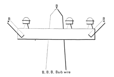
The transmission line from Canon City is a little less than 24 miles long. It is over a mountainous country and might be expected to be troubled from lightning, but there have been few interruptions from this cause. No static discharge wires are run on the line, but every 5 miles a bank of Wurts cylindrical non-arcing-metal lightning arresters are placed, 16 in series, on each line. They are enclosed in porcelain, put in a box and placed on a pole. Choke coils and a similar bank of arresters are put at each end of the line. The line is composed of three No. 3 copper wires on Mershon-glass insulators, 6 ins, in diameter, and triple petticoated. These have given good service, the only trouble experienced being an occasional crack in the glass between the tie wire and the pin through which the current leaks and burns up the pin. These cracks are usually due to people shooting or throwing stones at the insulators. The wires are spaced 50 inches apart, two on a cross arm and one on a pin on top of the pole. At corners the insulators are reinforced by a second insulator placed some distance away from the main insulator and tied to it. The results of the operation of this line have been very satisfactory as to reliability. Only one interruption of consequence has occurred in the past eighteen months. This was due to a bad location of the line in a creek basin. A mountain freshet washed the poles out from under the wires one night at 11:45. The next morning at 7 the damage was repaired and the line operating. Current is kept on the system 24 hours a day, every day in the year, and all repairs and alterations are made with current on the line. Since the washout spoken of the line was changed from the creek bed to a safer location without interruption of service. The plan adopted in changing insulators and handling the 20,000-volt live wire is to connect the live wire, which is to be handled, with a nail in the pole at a point below where the linemen stands when working with the line. This jumper makes a better ground than the linemans body, consequently he is unharmed. In a damp climate there might be danger of burning the pole up through the ground, caused by the jumper, but no such trouble is experienced in the dry climate of Colorado unless the jumper is left on too long. N. T. Wilcox, superintendent of the company, although somewhat doubtful at first as to the possibility of giving a reliable 24-hour service the year round over a single 20,000-volt circuit, now considers the line a success in that respect, and the service as reliable as that from any plant. That such results are being attained by a line of this voltage and length over the mountains is a matter of encouragement to all about to enter the long-distance transmission field. One man spends his entire time patrolling the long distance line. No small part of this companys success is due to careful, experienced supervision and maintenance of all lines and apparatus. The loss in the line and step-up and step-down transformations is 18 per cent. It is stated that since last summer current has not been off the 20,000-volt line a second. During the lightning season in the summer the line current sometimes follows a lightning discharge across the arresters and causes a partial short circuit for a few seconds. This interferes with the operation of the rotaries more than with any other apparatus. The 20,000-volt fuses for each transformer in the sub-stations are small copper wires, 23 ins. long, over which a soft rubber tube is slipped. These fuses are stretched between porcelain insulators. The insulators are mounted in rows on two rafters 23 ins. apart up near the roof of the sub-stations. These fuses are very successful as arc breakers. Facilities are provided for quickly cutting out a transformer and substituting the fourth or reserve transformer. Plugs cutting out the 20,000-volt primary fuses, for safety in replacing fuses, are put on the ends of long sticks for insulation. In case the fuses on one transformer blow, the other two legs of the circuit will usually carry the load for a short time until the reserve transformer can be switched in. Then the fuses can be replaced at leisure. The frequency employed on the system is 30 cycles. On the 2500-volt secondary circuit Stanley fuse blocks are used in which the fuse is passed through a hard fibre tube. An inspection of the 500-volt secondary distribution lines reveals the fact that lightning is a much dreaded enemy, even on low-pressure wires. The original plan for 500-volt pole lines was to put up a cross arm with three pins on it for the three-phase circuit and fasten barbed wire by staples directly on each end of the cross arm and to the pole top. The copper wire usually stretched more than the iron and in time a mixup between the two would result. Then brackets were put on the ends of the cross arms, as indicated by Fig. 2, and the barbed wire was put on the brackets. This was much better, but the present practice is to put the cross arm 18 ins. from the top of the pole and put a single barbed wire on top of the pole. The sub-stations require very little attention. One or more employes live near each. At No. I, is a storeroom, and a book-keeper is on duty during the day. At No. 2 an employe and daughter live, and the girl is able to replace fuses and take care of any ordinary trouble, or at least telephone to No. 1 if there is anything she cannot remedy. A solenoid relay is kept in the secondary circuits at sub-stations which sounds a gong in case current is cut off. A private telephone line is run under the 20,000-volt line from Canon City power house to the two sub-stations. The company now supplies about 125 properties (mining and milling) with power, or light, or both. All motors are induction type. The largest are 100 horse-power, of which there are four, all on continuous work. The hoists have motors ranging from 30 to 5 horse-power. There are 65 hosts connected. Lights in mines and mills number about 1500. In the district and on the 24-mile transmission line there are now 6 men employed. One of these has the duty of patroling the transmission line every other day. One mounted inspector is kept constantly on the go in the district looking over lines, apparatus and meters. The company owns and maintains nearly all the electrical apparatus, which it supplies with power, and charges a rental along with the power bill. Meters are the most prolific source of trouble as their locations around mines are not usually ideal, either as tu stability of support or freedom from dust. The result is they need constant attention. The Thomson meter is used. In spite of the large number of induction motors the voltage on the 500-volt network, as shown by a Bristol recording voltmeter chart at sub-station No. 1, is very small for a power circuit. The power house at Canon City has three units, consisting each of 30-cycle, 500-volt, 3-phase Westinghouse alternators direct connected to Hoover-Owens & Rentschler Corliss compound condensing engines, two of which are usually run. The exciters are independently engine driven. In the transformer room are four 500-kw step-up transformers for the transmission line. Each of the three transformers, regularly in service, has a double throw switch on its 500-volt primary side so that the load can be thrown from it to the reserve transformer on a moments notice. The 20,000-volt secondary circuits from each transformer can be opened by switches which give a 4-ft. break. In spite of the fact that the load consists largely of induction motors these switches open the 20,000-volt circuit satisfactorily, which contrasts somewhat with the experience of the La Bella plant, noted later in this article. A track runs alongside the transformers, so that any one of them can be slid out onto a truck and moved out on short notice. This feature is of value in case one catches fire. The switchboard is supplied with voltmeters, ammeters, indicating wattmeters and recording wattmeters, on both generator and totalizer panels. Automatic circuit breakers are used at the time the machines are thrown in parallel (they are always run in parallel), but on account of the sudden fluctuations of the load at occasional intervals the circuit breakers are blocked up after the machines are thrown in circuit and fuses are depended on entirely. H. H. Wilson, chief engineer of the plant has done considerable work in the way of experimenting with synchronizing schemes and now has a very simple and easily worked method. Instead of throttling the engine to get the unloaded machine in synchronism with the loaded ones before throwing in, an adjustable weight is put on the engine governor. The engineer starts up the engine, opens the throttle wide and then adjusts the weight on the governor until the machine is in synchronism. After the machine has been thrown onto the bus-bars the weight is put back to running position and the engine takes its share of the load. Another valuable attachment on the engine governor is an oil dash pot with a valve by which the governor can be made sluggish or sensitive. It is well known that it is easier to synchronize with a sluggish governor than with a sensitive one, because the variations in engine speed do not come so frequently. With an adjustable valve dash pot the sensitiveness can be adjusted at any time at will, This company has recently begun commercial incandescent lighting in Canon City in addition to its Cripple Creek load. This is done from the same bus-bars. Some may smile at this and have visions of a very fluctuating incandescent service, but the writer can testify that the night he spent at Canon City, in a hotel lit from this power house, there was much better service as to steadiness of light than there is in the majority of electric lighting plants. The service is supplied from the 500-volt bus-bars by a Scott transformation from 3-phase to 2-phase 2300 volts. Stillwell regulators are used in the light circuits. To operate the station 24 hours it takes 12 men, divided into eight-hour shifts. Six men are on the day shift and three men the other two shifts. The work of this successful company has been thus reviewed at length because of the many engineers who are figuring on transmission schemes of this nature at the present time. Although the conditions are somewhat exceptional the engineering results are worth knowing. The company, of which D. V. Donaldson, Colorado Springs, is president, is largely owned in that city. J. G. White, of New York, is also a director. N. T. Wilcox is general superintendent.
THE LA BELLA MILL, WATER AND POWER COMPANY
began operations in August, 1899. It derives its power from a steam plant, at Goldfield, in the midst of the Cripple Creek District. Being owned by parties interested in the Florence & Cripple Creek Railroad, over which most of the coal for the district comes, it is enabled to get its coal at a very much lower rate than other concerns in the district and is able to produce a kilowatt hour of electrical energy at figures that compare favorably with compound condensing plants in the central states. The station is well designed and equipped. Coal is brought in on a railroad siding above the power house roof and dumped into storage bins, from whence it is fed to traveling weighing-hoppers, and then to Babcock & Wilcox automatic chain grates under Babcock & Wilcox water tube boilers. A crusher is also provided for emergencies. The coal handling machinery was furnished by C. W. Hunt & Co. The generating units are McIntosh & Seymour compound condensing, medium speed engines direct connected to 600-kw 3-phase 6600-volt General Electric revolving field generators. Two units are running and a third going in. The switchboard is about to be changed to a more satisfactory arrangement than that at present in use, The main, circuit-breaking, 3-pole switches in the 6600-volt mains are of the type carrying a copper and a carbon contact on the end of a long stick and giving a 33-inch break. Owing to the inductive effect of the large number of induction motors on the power circuits this 33-inch break is not always sufficient to break the arc and it streams across the gap to the detriment of everything around. In place of these, oil break switches will be put in and all 6600-volt wires will be kept off the switchboard and the high tension switches placed below the board instead of passing up the back of the board to switches at the top of each panel in dangerous proximity to the low voltage instrument wires, as now. The company sells power to electric lighting sub-stations, owned by a separate corporation, at eight towns; Cripple Creek, Victor, Goldfield, Independence, Altman, Cameron, Gillette and Anaconda. The 6600-volt current is taken direct to sub-stations in each town where it is transformed to 110 volts on a 3-wire system. A trouble man is kept at each sub-station to look after lines and transformers. In one station direct current arc machines are driven by induction motors. Seventeen mines and five sampling mills are supplied with current by this company. The company usually makes a contract with the mines, which includes maintaining all the electrical apparatus as well as supplying power. It also runs an air compressor in its power plant for near-by mines. In some cases the electrical apparatus is bought by the mines, in others simply rented. The principal power business is driving air compressors and hoisting. The hoists are General Electric induction motors connected through friction drive to a winding drum. In starting the motors resistance is put in the armature circuit, which is subsequently removed. The distribution over the district is at the same voltage as that of generation, viz., 6600. Two cross arms are used on a pole line carrying a single 3-phase circuit. On the lower cross arm are three pins with insulators for the 3-phase circuit. On the top cross arm are three barbed wires for lightning protection, which is grounded as frequently as a good ground can be found. This company is under the general management of Asa Fisher, vice-president, and Herbert S. Sands is chief engineer.
THE PIKES PEAK POWER COMPANY.
This company is one of the companies controlled by the Woods Investment Company, which owns various mines, mills and other properties in the district. The chief engineer of the undertaking is R. M. Jones, formerly of Salt Lake City. A water power, coming from the western slope of Pikes Peak, is being developed. Most of the work is done, with the exception of the power house. Water, under about 1000 feet head, will drive 4 Pelton wheels direct connected, each to General Electric 400-kw 3-phase generators. The transmission voltage will be 12,000. Much of the power supplied by this plant will be used in the Woods Investment Companys various properties.
|