Cataract Power Co.'s plant at De Cew Falls for power at Hamilton, Ontario
|
[Trade Journal] Publication: The Electrical Engineer New York, NY, United States |
|||||||||||||||||||||||||||||||||||||||||||||
|
The Hamilton, Can., Cataract Power Co.'s Plant at De Cew Falls.
BY GEORGE W. BOWIE.
THE starting of this plant is an event that all the prominent hydraulic and electrical engineers in Canada have been looking forward to for some time past with interest on account of the many novel features embodied in its construction. The engineers selected for this purpose to conduct, design and overcome the obstacles which arise with a departure from the customary methods, to suit location, conditions, etc., are well known, and occupying the front rank in their respective professions, as men of unquestioned ability, as proven by the result of the "formal opening" and celebration on the 12th of November at the power house, at De Cew Falls, three miles from St. Catharines, of the transmission of electrical energy to the City of Hamilton, 34 miles distant. The celebration was participated in by members of the Ontario Legislature, business men of Hamilton, hydraulic and electrical engineers, from widely scattered points of the Dominion of Canada and the United States, who were there to witness the termination of a stupendous work and the successful culmination of the hopes of the directors and stockholders of. the Cataract Power Company, of Hamilton.
It has been proved beyond a question of doubt, that for simplicity, economy and profitable results, water power can often outbid steam, and is by far the most satisfactory method yet known of utilizing nature's forces for the comfort and welfare of the people adjoining those water powers, with its applications to the industries necessary for the employment of the human race.
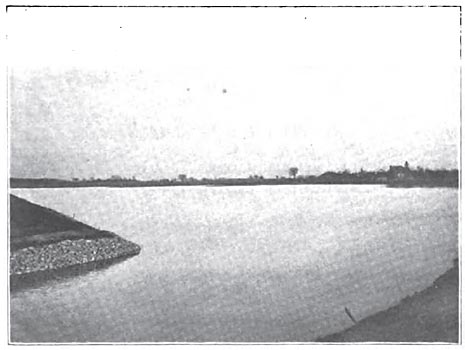
THE CANAL.
Beginning with the canal along which the water flows for creating this electrical energy, the water is admitted into the company's canal from the Welland Canal at Allanburg, four miles distant from the power house, and is admitted at the same elevation as the water of Lake Erie. In the Cataract Power Company's canal the water is carried to the brow of the mountains at the De Cew Falls, where the canal terminates with massive concrete walls. Along the line of the canal are three lakelets covering a space of 30 acres (known as Lakes Moodie, Gibson and Patterson, respectively), with a capacity to keep the plant running 48 hours, if repairs should be found necessary along the water-way at any point. This part of the work showed the skill and perseverance of the engineers, Mr. W. Kennedy, Jr., of Montreal, consulting engineer for the company, and Mr. T. J. Hillman, resident engineer, in overcoming natural obstacles and adapting the contour of the country, through which the canal passed, to attain their object.
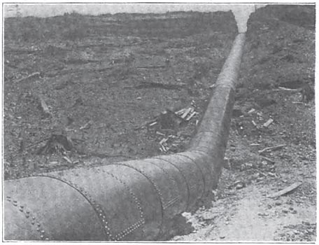
FEEDER PIPE.
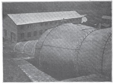
Overlooking the brow of the mountain where the canal ends, you look down the slope on which rests the leviathan steel feeder pipe, which conveys the water to the turbines. The pipe has capacity for 10,000 h. p., and the water flows through it with a velocity of three feet per second, when supplying 6,000 h. p.
The upper end of the pipe is buried beneath a mass of concrete, which embeds, or anchors itself, in the interstices of the rough rock, on each side and the bottom, and holds the upper end or top of pipe, anchored and immovably fixed to the end wall of the canal. The pipe is approximately 700 feet long outside of the power house, and the various lengths and thicknesses of plate used in its construction are as follows:
286 feet, 9/16 inch thick; diameter, 8 feet 100 feet, 3/8 inch thick; diameter, 7 feet, 6 inches 71 feet, 7/16 inch thick; diameter, 7 feet. 231 feet, 1/2 inch thick; diameter, 6 feet, 10 inches.
At the end of this last diameter is the beginning of the elbow which enters the power house, and gradually enlarges in diameter within a radius of 35 feet from 6 feet 10 inches diameter to 8 feet 6 inches diameter of steel plate 3/4 of an inch thick, to enable it to stand the pressure of 113 pounds to the square inch, also the fluctuating pressures arising from street railroad service.
Inside the power house the feeder pipe is 70 feet long, and is gradually reduced in diameter as it approaches the last wheel, it then being 6 feet 6 inches diameter. It terminates in a cone, whose smallest end is 12 inches diameter, and is extended to feed two 35 h. p. turbines which run the exciters.
The feeder pipe on the circular and vertical seams is double rivetted, the longitudinal seams are triple rivetted; all rivets are 1 1/8 inch diameter, and all seams are butt strapped. To compensate for the variations of length of such a long pipe, due to the extreme heat and cold of summer and winter, midway up the slope is situated an expansion joint, whose maximum movement from change of temperature will be about 6 inches.
THE POWER HOUSE.
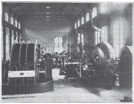
This is a substantial structure, composed of skeleton iron work, filled between with brick. The dimensions are: Length, 174 feet; width, 42 feet; height to apex of roof, 38 feet. The floor is of solid concrete, 12 inches thick, with a surface layer of cement 3 inches thick, and the interior of the building is abundantly supplied with light from its numerous windows, as shown in the illustration.
The visitor on entering the power house is at once impressed with the symmetrical arrangement of the generators, water turbines, transformers and switchboards, and the brilliant illumination from 200 incandescent lights. The water turbines, as being next in sequence of description, are as follows: There are two Victor water wheels (with provision for two more), and in connection with this plant the significant feature is that the descent is 260 feet from head water to tail water. The wheels are special 44 inches diameter, the journal bearings are 7 3/8 inches diameter, and run at 400 revolutions per minute, while at a test made a few days ago, one of the wheels developed 1,800 h. p. The water is admitted to the wheel from a cylinder gate, which is encircled with water in a water jacket around the case of the wheel.
The water wheel or hydraulic part of the plant is isolated from the generators with a 3 inch space between the couplings (which connect the water wheel and the generator) by leather links, whose studs are alternately fastened to each half of the coupling, thereby preventing the current from grounding through the water wheel. There are many salient points worthy of observing in connection with this hydraulic planthigh head, high speed, all necessitating a high safety factor in its construction, and a departure in design from the usual routine of water wheels situated between the turbine and the branch pipe. Coming through the floor from the main feeder pipe is a 36-inch gate valve, which in the operation of opening and closing has to slide against a pressure of 60 tons, making a full movement in 25 seconds. It consists of a vertically placed cylinder, whose piston is affixed to the gate valve disc by rods, and by the admission of water above or below the piston, at 113 pounds pressure to the square inch, the gate valve is accordingly raised or lowered. To prevent rupture or water hammer, each gate valve has attached a relief valve with a spring adjustment. The relief valve is also brought into service when large loads are thrown off or on the generator. Each unit is provided with a momentum wheel on the turbine shaft, which weighs 7^ tons, constructed out of steel plate, the rim of the wheels being made from whole plates with the interior cut out and two whole plates being left intact to form the web. In this manner is obtained a momentum wheel that practically cannot fly asunder from centrifugal force. The onlooker is impressed when looking at the water wheels and generators attached, with the massive and substantial nature of the mechanical equipment, which runs so smoothly, without jar or tremor of any description, on account of the perfect alignment and balancing of the revolving parts. Each water unit weighs about 60 tons. One of the most interesting features in connection with the plant is the Giesler mechanical-electrical governor, which regulates and keeps a practically steady speed on the water wheels and generators, irrespective of amount of change of load. The hydraulic plant, including power house, feeder pipe and water turbines, with their attachments, was designed by Mr. A. C. Rice, mechanical and hydraulic engineer, Dayton, Ohio. To facilitate the handling of such heavy machinery there is an overhead travelling crane of 15 tons capacity.
THE ELECTRICAL INSTALLATION.
This consists of two S. K. C. two-phase inductor type generators (built by the Royal Electric Co., Montreal, P. of Q.); rated capacity, 1,000 kilowatts at 2,400 volts; weight, 60 tons each. These machines are run in parallel, and supply current to 10 step-up transformers, which raise the voltage to 22,000. The transformers are of 200 k. w. capacity each, and are of the oil-insulated, water-cooled type. They feed the main line to Hamilton, consisting of four No. 1 B. and S. gauge hard-drawn bare copper wire, supported on the poles on triple petticoated porcelain insulators, every one of which was tested at 60,000 volts before being used. At Hamilton the current is received at a transformer sub-station, where the pressure is reduced to 2,250 volts by oil-insulated, air-cooled transformers. It then goes to the distributing switchboard, from which it feeds the lighting and power circuits throughout the City of Hamilton. Details are given below separately. The exciters are rated at 30 k. w. at 70 volts, and run at 1,000 revolutions.
SWITCHBOARD DETAILS.
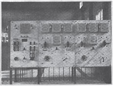
The main switchboard, as is shown in the cut, is made up of three white marble panels, one for each generator and one for the exciters. On the generator panels all the connections are made on the back of the boards, there being no bare terminals on the face. The switches are of the slide quick-break type, and are provided with automatic shutters to prevent arcing. They are double throw, connecting to two separate sets of bus bars, so that the machines may be run on separate lines or in parallel, according to the future requirements of the service. Each generator panel contains a voltmeter with a double-throw switch connected to both phases, an ammeter on each phase and a direct current ammeter in the field circuit of the generator. The cases of the instruments are made of ground glass and present a very attractive appearance. No fuses are placed on the generator, as with this type of machine it is considered safer to risk the overload due to a short circuit rather than have the load constantly removed entirely from the water wheels by the blowing of fuses. The exciter panel contains the usual instruments for operating two shunt-wound machines in parallel, and also contains a synchronizer which is of the ordinary three-lamp type.
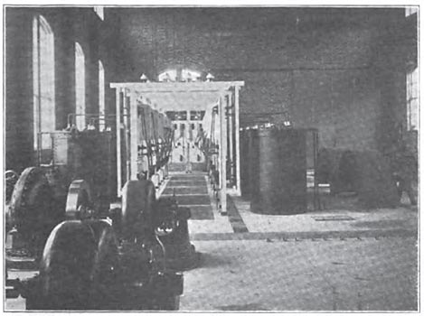
Immediately back of the switchboard is the space, taking up one end of the building, occupied by the step-up transformers. These transformers, of which there are ten, are arranged in batteries of five, each transformer having a capacity of 200 k. w. They are artificially cooled by means of water pipes supplied direct from the pen stock, the pressure being reduced by means of throttle valves. The transformers are encased in tanks made of steel boiler plate, and rest directly on the concrete floor. The coils are wound in sections, carefully insulated and separated by extraordinary air space, and the whole immersed in mineral seal oil. This construction has been found to answer admirably the purpose of this exceedingly high voltage, each transformer being tested with a break down strain of 40,000 volts before being installed. A novel feature of the installation is the switchboards which accompany each transformer. They are of specially selected white marble, and contain two single-pole high voltage switches and one double-pole 2,000 volt switch. The two high voltage switches are separated by a marble barrier. The 22,000 volt switches consist of a flexible cable having a screw plug attached to one end and a socket to the other, the socket being attached to a hard wood pole 4 feet in length for safe handling. The socket and the plug which it fits over are tipped with non-arcing metal. By means of these specially connected switches the 22,000 volt circuit can readily be opened, although in practice it is usual to throw load off the transformers by means of the low voltage switch, so that the high voltage switch is only required to break the leakage current of the transformer. The low voltage switches are of the back-of-the-board slide type. Each transformer is also equipped, on both the primary and secondary sides, with non-arcing fuses. The 2,000 volt wires inside the building are all covered with a specially heavy insulation of rubber, and are supported on porcelain line-insulators on an overhead rack, all being in plain sight and easily accessible.
THE TRANSFORMING ARRANGEMENTS.
From the transformers, which are connected five in parallel on each phase, the circuit runs to the line terminal board, consisting of four high voltage switches similar to those placed on the transformer switchboards, except that they have double terminals, in order that they may be changed to either of the two lines contemplated by the company. Immediately above the line terminal board is placed a specially constructed lightning arrester, composed of 60 S. K. C. non-arcing 2,000 volt arresters, connected in triangular form. From the lightning arrester the wires pass upward and out through the wall of the building at a height about 30 feet from the floor. The company's step-down station is located at Victoria avenue, immediately beside the Grand Trunk Railway's right of way, about one mile within the city limits. It is a neat structure, built of brick with slate roof, and specially designed for this purpose. At this point the voltage is reduced to 2,000 volts, at which pressure the current is distributed through the city in four separate circuits. The line wires are carried through the brick walls of the building in the same manner as at the power house. There is the same arrangement of lightning arresters, high voltage lines and two batteries of transformers. The transformers, however, are arranged so as to be artificially cooled at times of heavy load by means of an air blast. The transformers rest over an air duct in the floor and are provided with a ring of vertical air ducts passing up through the oil. The blast arrangement, which consists of a No. 6 Sturtevant blower, direct connected to a two-phase induction motor, delivers air directly into this duct, which then passes upward through the transformers. In the transformer room is also placed the distribution switchboard and, as at the power house, only half the ultimate capacity of the transformers has been installed, the building being designed to accommodate two more batteries of five, similar to those already placed, consisting of four panels each, containing two ammeters, two double-pole double-throw switches and four duplex fuse blocks. One circuit which supplies the incandescent lighting current for the Hamilton Electric Light & Power Co., is placed on a separate bank of transformers in order to keep the incandescent service distinct from the motor circuits. From the switchboard the circuit wires pass upward to a cupola in the roof, at which point they are joined to the distribution circuits. The line supplying the incandescent service is a four-wire, two-phase circuit, but the circuits devoted exclusively for power are composed of three wires only. At the premises of the Hamilton Electric Light & Power Co. is being installed a new circuit switchboard, arranged to accommodate the old single-phase lighting circuits of this company. Each circuit is equipped with a double-throw switch, in order that the load may be balanced between the two phases, and each phase is provided with a regulating transformer, in order that the pressure may be controlled from this point. The old house-to-house 1,000 voltage, 16,000 alternation transformers, have all been replaced by new S. K. C. 2,000 volt, 8,000 alternation transformers in larger units, and the service all changed to this higher pressure, in order to reduce the losses and retain better regulation. In addition to supplying the Hamilton Electric Light & Power Co.'s service, the Cataract Power Co. have already contracted for a large amount of power for operating factories of different kinds in the city. They expect, within a short time, to supply the various electric railways in and about Hamilton, and to replace nearly all the steam engines in the various manufacturing establishments with electric motors. The plant has been in practical operation for several months, and thoroughly demonstrated the success of electrical transmission at this high voltage and long distance, which speaks wall for the carefulness in designing and construction of the work.
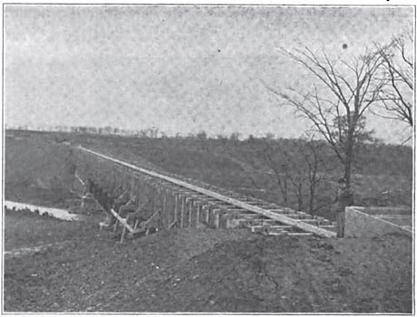
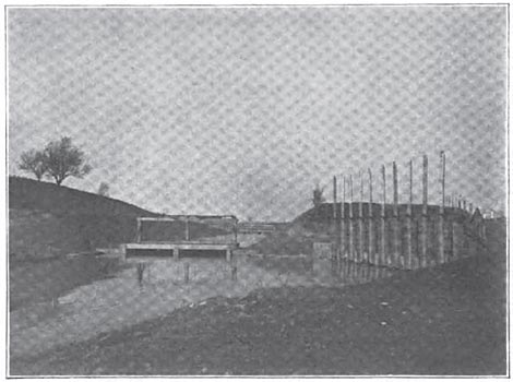
THE TRANSMISSION LINE.
The high voltage wires are carried through the brick wall forming the gable end of the power house, by means of lead-covered rubber cable, protected by vitrified pipe, the cable being kept clear of the pipe by wooden bushings specially prepared in oil. After crossing over a cross-arm attached to the building the lead-covered cable is joined to the bare copper transmission wires, by means of a long, carefully made, waterproof joint. This special construction has proven entirely satisfactory.
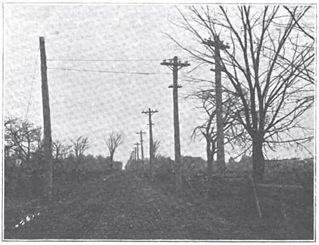
From the power house the transmission line crosses the Twelve Mile Creek and runs up the hill opposite on private property, to a concession road, thence along this roadway due north to the Grand Trunk Railway, and then westward along the railroad right of way on an almost perfectly straight line to the company's step-down station at Hamilton, a total distance of a little less than 34 miles. The transmission wires are four in number and are No. 1 B. & S. medium drawn copper. They are all placed on one four-pin cross-arm, 3 3/4 x 5 3/4 inches, spaced 18 inches apart, and are supported on porcelain insulators of the Redlands type, supplied by the Imperial Porcelain Co. The pins are of special design, holding the insulator two inches higher from the cross-arm than the standard practice. This is to avoid trouble from heavy snow or sleet. The pins are of yellow locust, specially prepared in oil, and are fastened into the cross-arm with a wooden pin instead of being nailed, so as to use as little iron as possible. The poles are all specially selected, 8 inches at the top and not less than 35 feet in length. They are set go feet apart and 6 feet deep in the earth. The height of the pole varies with the contour of the ground, so as to keep the wires as nearly horizontal as possible. At marshy places, a crib filled with stone is built around the base of the pole, and where the line crosses the Jordan River, the poles are placed in a cluster of piles specially driven for the purpose. On the top of the poles is run a galvanized iron barbed wire, grounded at every pole by means of an iron plate for lightning protection. Below the transmission cross-arm is placed a two-pin cross-arm carrying the telephone circuit. The telephone circuit is a complete metallic circuit of No. 10 B. W. G. galvanized wire, transposed at every fifth pole. This arrangement has been found to give satisfactory service with the heaviest currents yet passed over the line. The insulators were all carefully tested with a break-down pressure of 60,000 volts, both at the factory and again at Hamilton, before being put up, with the satisfactory result that not one has broken down, or produced the slightest trouble in the three months during which the line has been in operation, notwithstanding the unusual rain and sleet storms during that period. The line was constructed by Messrs. Lowe & Farrell and is a very creditable piece of work.
PERSONNEL OF THE WORK.
The contractors and engineers engaged in this work are ns follows: Messrs. Macdonald & Sutherland, canal excavations and brick work and foundations in power house, Messrs. Stillwell, Bierce & Smith-Vaile Co., Dayton, Ohio. Feeder pipe and frame work of power house (built by Hamilton Bridge Works) designed along with the hydraulic plant bv Mr. A. C. Rice, engineer for the Dayton firm, who contracted for all the iron work and machinery. It was erected under the supervision of Mr. Geo. W. Bowie. The generators and electrical appliances were furnished by the Royal Electric Co., of Montreal, and were erected under the supervision of Mr. W. C. McLaren. The credit of this scheme is due to Mr. Jno. Patterson, who realized the possibility of and the benefit to be derived from the development of this enterprise for the industries of Hamilton. The capital of the Cataract Power Co. is $1,000,000. and it is organized as follows: Hon. J. M. Gibson, president; Mr. James Dixon, vice-president; John Moodie, secretary-treasurer; Jno. Patterson, secretary; H. R. Leyden, general manager; Directors, Jno. L. Dickenson, J. W. Sutherland, Jno. Knox, J. J. Wright, of Toronto; J. A. Kamarar, of Toronto.
|