[Trade Journal]
Publication: Electric Journal
Pittsburgh, PA, United States
vol. 8, no. 10, p. 830-846, col. 1
THE HOOSAC TUNNEL ELECTRIFICATION
H. K. HARDCASTLE
IN September, 1910, it was decided to electrify the Hoosac Tunnel and approaches including the yards at each end. On May 18th, 1911, the first train was drawn through by electric power, while continuous electric operation of the total traffic was begun on May 27th.
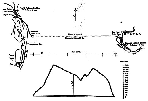
The Hoosac Tunnel is the longest tunnel in the United States, being 25,081 feet long from portal to portal. It pierces the mountain range between the Hoosic and the Deerfield Rivers in the Berkshire Hills, its location and the general arrangement of tracks being shown in Figs. 1 and 2. Where the rock is soft the tunnel is arched with brick, but in the greater part the rock is hard and the walls are bare rock. To drain off the large amount of water en countered, the tunnel was run on a grade of 26.4 feet to the mile from each portal to a short level stretch in the center, at which point a 1,028 foot shaft extends to the top of the mountain for ventilation. The work of digging this tunnel was started in 1851, and the first train went through February 9th, 1875. It is straight and double tracked from end to end and cost about twelve million dollars.
The electric zone extends from the little tunnel west of the North Adams station to a point about a quarter of a mile east of Hoosac Tunnel station, the total distance being 7.92 miles. The electrification includes the yards at North Adams, about two miles of the main line between North Adams and the west portal where the grade is about 0.75 percent; then 4.75 miles of the tunnel which was constructed on a 0.5 percent grade leading from both ends up to the central shaft, and the yards at the east portal, including three-quarters of a mile of main line, having a grade of about 0.5 to 0.7 percent. In all 21.31 miles of single track is electrified.
The traffic at this point has been exceedingly heavy and with the smoke and steam incidental to steam operation, the tunnel has long been the limit of the capacity of the division, besides being exceedingly dirty and disagreeable to passengers. With the tunnel electrified automatic block signals have been installed and the capacity of the tunnel increased three-fold by allowing three trains on the same track at the same time. This was not safe before, as signals would not have been visible. Instead of being a nuisance the tunnel has become a pleasure in summer on account of its coolness and all passenger trains go through with the windows open.
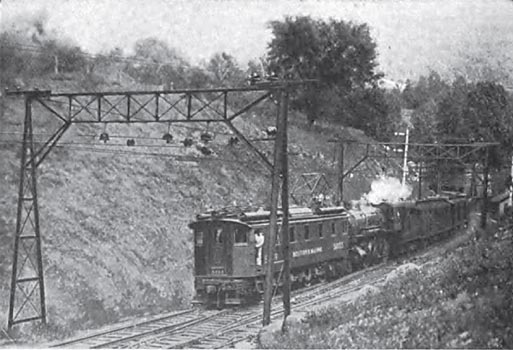
The method of operation is for the electric locomotive to couple on in front of the steam locomotive as shown in Fig. 3, and pull the train, locomotive and all through the tunnel. Meantime the fires of the steam locomotive are left undisturbed so as to avoid filling the tunnel with smoke and gases. The success of this method is daily demonstrated, for it is usually possible to see out from the central shaft, a distance of 2.37 miles.
| |||
| Fig. 2Plan and Profile of Hoosac Tunnel |
Overhead single catenary construction for 11,000 volts single phase was chosen as the system best adapted for this electrification, and the equipment is in many respects similar to that of the New York, New Haven and Hartford Railroad between Woodlawn, N. Y., and Stamford, Conn.
POWER HOUSE
The power house has been built at Zylonite, about 2.5 miles south of the west portal of the tunnel. It is located near the old power house of the Berkshire Street Railway and uses a pond back of this station to supply cooling water for the condensers. From this location it will be possible to supply power to the street railway system without additional transmission lines if it is decided to abandon the old power house, and the station can be used entirely for this purpose if a hydro-electric plant is later built on the east side of the tunnel to supply the railroad. Water for the boilers is furnished by ten artesian wells 100 feet deep, and the coal is brought in from a switch on the Boston & Albany Railroad.
| |||
| Fig. 3Electric Locomotive Drawing Steam Locomotive and Train Out of Tunnel |
The building is of brick on a concrete foundation 100 by 200 feet and is about 80 feet high. The basement floor is on a level with the ground, and is divided into three sections. The section at the east end or boiler room basement contains the Worthington duplex boiler feed pumps, the forced draft apparatus consisting of two steam turbines driving Sturtevant blowers, and the ash hoppers and ash cars. The middle section, or engine room basement, contains two Westinghouse-LeBlanc jet condensers, a service pump, the oil filter and gravity oil system, a battery room containing a 120 ampere-hour storage battery, transformers for supplying the lighting system and power for the station apparatus, and a machine shop.
The section at the west end contains the switch house. Here are located the two 60 000 volt oil circuit breakers, with heavy grid resistance and impedance coils to prevent excessive current during a short-circuit. The grid resistance is in shunt with automatically operated oil switches, so connected as to cut the resistance in series with the line load when a short-circuit occurs. The resistance is of such a value as to limit the current on a dead ground to 600 amperes which the main circuit breaker then interupts, thus completely opening the short-circuit.
On the second floor is the boiler room, which extends to the roof, and contains four 500 horse-power water tube boilers, equipped with underfeed stokers, the stokers being operated by a chain belt from the forced draft apparatus. Each boiler is supplied with a superheater which superheats the steam 100 degrees F. The other boiler room equipment includes a Sturtevant staggered tube economizer, two 12-foot induced draft fans, a feed water heater, a feed water weigher, two traveling combined hoppers and weighers for coal, and a service water tank which supplies gland water to the turbines, the jacket water for the compressor and water for the wash rooms. Space has been left in the boiler room for four additional boilers with their necessary equipment.
The coal is unloaded from hopper cars into a receiving bin under a trestle. From this it is raised 75 feet to the roof by a bucket conveyor, shown in Fig. 4, of 40 tons per hour capacity. Here it passes through a crusher to a 75 ton storage bin. Both the conveyor and crusher are operated by 20 horse-power induction motors.
| |||
| Fig. 5Power House and Spray Cooling System |
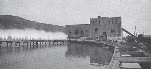
As mentioned above, there is a pond near the station from which cooling water is taken for the condensers. In order to keep down the temperature of this pond a spray cooling system has been installed. This consists of two sprays or pipe lines about three hundred feet long mounted above the pond, Fig 5, from which the water is pumped through no spray nozzles. The water is pumped through the spray system by a centrifugal pump driven by a 100 horse-power induction motor. There is also an engine driven pump for use in emergency. The cooling water for the condensers is drawn in from the upper end of the pond, and discharged through a long flume leading to the lower end. The pumps supplying the sprays draw water from the discharge of the condensers and what is not used in the sprays goes out through the flume.
Like the boiler room, the engine room extends to the roof. In contains two main units, each consisting of an 11 000 volt, three-phase, 3,750 k.v.a. (single-phase rating) generator coupled to a double-flow steam turbine. The auxiliaries consist of a 100 kw steam turbine exciter unit, a 100 kw motor-driven exciter, a small motor-generator set for charging the storage battery, an air compressor and a 30-ton hand operated crane.
One end of the power house is given over to the switchboard alcove and the rooms containing the remote control switching apparatus, the lightning arresters and the chief engineer's office. The switch board is set at a slight elevation above the engine room floor. It is a dull finish slate board with eleven panels. All 11 000 volt circuits are controlled by oil switches operated from the board by remote control. The generator voltage is regulated by two Tirrill voltage regulators.
A diagram of the electrical layout is shown in Fig. 6. One phase of the generator supplies the trolley load, one phase the power load and one phase goes to ground. The Berkshire Street Railway, however, is supplied by an ordinary three-phase transmission line. For the railway locomotive system there are a set of three-phase station bus-bars and four separate feeder bus-bars which receive power through oil circuit breakers from the main bus-bars. The "trolley" bar of the feeder bus-bars furnishes power for the electric locomotive load and the "control" bar furnishes power to operate the circuit breakers which control the various sections of the track at the west portal and at the repair shop. The "trolley" and "power" lines are protected by an electrolytic lightning arrester, and the "control" line by a low equivalent lightning arrester. The "power" phase of the feeder bus-bar also furnishes power to a feeder for the hand-control operation of the circuit breakers at the switch houses. A reactance coil is located between the main station bus-bars and the feeder bus in the "power" and "control" phase to prevent excessive current during a short circuit.
This may be made clearer by assuming a short-circuit, say a flash-over of a pantagraph insulator, on one of the locomotives somewhere on the line. The rush of current through the series transformer in the switch house operates relays which make the connections between the ''control" wire and the mechanism operating the section breaker in the switch house which controls that particular section. The section breaker does not open, however, as the control wire is not yet energized. The rush of current then operates an overload relay at the power-house which opens the switches in succession cutting a heavy resistance in series with the trolley phase. At the same time the overload relay has operated a switch which energizes the control wire and thus, as the proper connections have already been made at the switch house, as mentioned above, the proper circuit breakers open to cut off current from this section. If for any reason these circuit breakers at the switch house do not open the circuit at the end of a given interval the switches at the power house will open, removing all power from the trolley phase.
TRANSMISSION LINE
The current is transmitted at 11,000 volts from the power house to the switch house at the west portal over a double circuit' transmission line 2.42 miles in length. The corner towers, Figs. 4 and 7, are formed of four uprights made of angle-iron strengthened by angle-iron cross pieces and diagonal braces. These uprights support at their top an angle-iron frame work on which are mounted the porcelain insulators that support the wires. The uprights are set in concrete foundation piers. The towers along the straight part of the line are formed of two eight inch channels connected together by angle-iron braces and diagonals and tied together by a cross piece at the top. These towers carry two angle-iron crossarms and are supported on two concrete foundation piers set at right angles to the direction of the line. They are spaced about 300 feet apart on the level.
The transmission line consists of five stranded copper cables, two of which carry current for the trolley or locomotive load and are suspended from the cross arms at one side of the tower, while the power and control wires are suspended in a similar manner from the other side. The cross tie at the top of the tower carries an insulator to support the ground wire which also serves as a guard wire protecting the transmission line against lightning. The line terminates at the switch house at the west portal which controls the entire system. The switch houses at the east portal and at the repair shop are not connected to the transmission line, but are fed through the trolley wires of one or both main tracks. Therefore, as long as current is on either one of the main track trolley wires the remainder of the system can be operated.
The same towers which carry the transmission line also carry two telephone wires supported on one of the cross braces between the channels about ten feet below the high-tension wires. Noise due to inductance on the telephone line is prevented by frequent transposition of the wires, the two wires being turned through 90 degrees between each tower. The effect of inductance is further reduced by one-to-one transformers put in series with the line, one wire being led through the primary and the other through the secondary. The static charge is taken off through impedance coils connecting the two telephone wires, the center point of the coils being grounded.
| |||
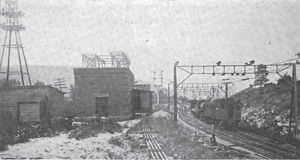
| Fig. 7View of Switch House and Overhead Construction at West Portal |
OVERHEAD CONSTRUCTION
Outside the tunnel two different systems have been used to support the overhead line. For two and three track sections on the main line the supporting bridges are built-up trusses of the type shown in Fig. 7, formed of seven and eight inch channel top and bottom chords with light angle posts and double diagonal rod braces in each panel. These bridges are supported at each end by A-frame towers formed of two eight inch channels braced with light angles, the plane of these towers being parallel to the center line of the tracks.
In the yards, where more than three tracks are equipped with overhead wires, instead of the steel bridges, cross catenary span wires are suspended from the apex of A-frame steel towers built of eight inch channels, with their sides in a plane at right angles to the track, Fig. 8. The messenger cable insulators are suspended from these stranded steel cross catenary cables by stranded steel wires of suitable length. Each tower is grounded by a cable clamped to the apexes of the towers. The anchor bridges are box trusses supported on heavy A-frame towers with latticed sides stiffened with double diagonal braces.
| |||
| Fig. 8Cross Catenary Line Construction in Yards at North Adams |
The overhead trolley system is sectionalized into twelve units consisting of two tracks in the east portal yards; east bound main track and west bound main track of the east portal; east bound and west bound tracks of the tunnel; west bound main track from the west portal to the west end of the North Adams yard; a section of the east bound main track and a cross-over opposite the west portal switch house; two sections of the long siding between the North Adams yard and the west portal switch house; the shop yard; four tracks in the North Adams yard, and the east bound main track from the west end of the North Adams yard to the west portal switch house.
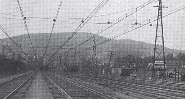
An interesting point in the overhead construction is the crossing of the double track 11,000 volt alternating-current railway trolley and the single track 600 volt direct-current trolley lines of the Berkshire Street Railway, just west of North Adams station. A view of this crossing is given in Fig. 9. The 600 volt trolley is sectionalized with wooden section insulators eight feet long on each side of the crossing, and is carried over the crossing under an inverted five inch channel which is supported by stranded steel cable span wires. This channel iron is on the same plane as the 11,000 volt alternating-current trolley wires but is insulated from them by similar eight foot section insulators. The direct-current trolley wire in this crossing section normally carries no current. On the north side of the crossing a feeder is connected to the 600 volt trolley wire and carried to a switch on top of a wooden pole. When this switch is closed by pushing up on a rod, 600 volt direct-current is fed to the crossing channel and trolley wire so as to permit a street car to pass over the crossing with current on. When the rod is released the switch opens by gravity, and by making another contact, grounds the channel iron and the direct current section of the trolley. The section insulators in the 600 volt trolley are grounded at the center of their length so that the 11,000 volt current can not leak past them in case of breakdown of any of the 11,000 volt section insulators.
The messenger cable outside the tunnel consists of a five-eighth inch stranded steel cable which supports a No. 0000 grooved copper conductor by rigid hangers of varying lengths at intervals of ten feet. The contact wire, which is No. 0000 grooved Phono-electric, is carried 1.75 inch below the copper conductor by double clips attached in the center of the ten foot spans between the hangers. On curves the conductor and contact wires are both suspended from the messenger by inclined hangers having double clamps.
| |||
| Fig. 10Overhead Construction in Tunnel |
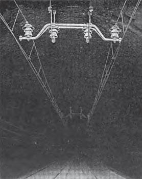
Inside the tunnel on account of the small clearance and the great amount of moisture present, the erection of an 11,000 volt trolley presented quite a problem. The supports are 100 feet apart and consist of U-shaped brackets parallel to the track, held in place by 1.25 inch wrought iron bolts extending 18 inches into the rock or brick arch. These bolts were split at the upper end and hammered home on a wedge, but prior to setting the bolts, the holes were filled with cement, and the cement rather than the wedges being relied upon to hold the bolts in place. Two U-pieces support a bracket of the type shown in Fig. 10, by means of two 150,000 volt triple petticoat porcelain insulators and these brackets, which extend across the track, in turn support the messenger cable through 150,000 volt insulators. As these primary and secondary insulators are in series, the combined dielectric strength is 300,000 volts.
Owing to the limited clearance in the tunnel the two contact wires are lowered to 15 feet 6 inches above the rails. For the same reason the messenger cables are supported 14 inches inside the center line of the track. This gives a minimum clearance of 12 inches between the messenger and the roof of the tunnel. In order to provide maximum conductivity a five-eighth inch stranded copper wire cable is used for a messenger. The twin contact wire hangers are designed to allow some vertical movement of the trolley wires. All parts of the tunnel hangers are made of bronze.
DIFFICULTIES OF THE WORK
The difficulties encountered in erecting the overhead construction in the tunnel without seriously interfering with the traffic must have been seen to be appreciated. The fact that it has heretofore been costing about two dollars to replace a tie owing to the fact that often the men could work only a couple of hours in the whole day, and that it was a common occurrence to have men brought out unconscious, owing to the bad air, may indicate something regarding the conditions in the tunnel.
To reduce the amount of smoke and handle the heavy freight trains during the work of construction, the railroad company purchased four large Mallet compound oil burning engines. The erection work was done by men on two specially constructed work trains each consisting of an oil burning locomotive, two locomotive tenders, a box car containing blacksmith's forges and anvils, an air compressor car, thirteen platform cars on which were built working platforms eleven feet above the rails, a coach fitted up as a dining car and a freight caboose. The trains were piped for compressed air supply and thoroughly lighted by electricity. On the floor of every third platform car a wooden air lock was built into which the men could retreat during and after the passage of a train. An air valve was provided inside these locks which, when partially opened, created sufficient pressure to keep out the smoke and gases, and provided fresh air for the men in the lock.
The construction work in the tunnel included the drilling of 1,000 holes, 2.5 inches in diameter and 18 inches deep, in the roof of the tunnel for the catenary hangers; 1,500 holes 1.75 inches in diameter and six inches deep in the side walls for telephone and signal cable hangers; the drilling and blasting down of the rock roof of the tunnel in many places to obtain the necessary clearance, and erecting the messenger and trolley wires.
In order to make the working conditions as good as possible the large fan at the top of the central shaft was run continuously, and the two work trains were kept on opposite sides of the shaft with their locomotives coupled to the end nearest the shaft so that the men would not be bothered by the smoke of either locomotive.
| |||
| Fig. 11Electric Passenger Locomotive |
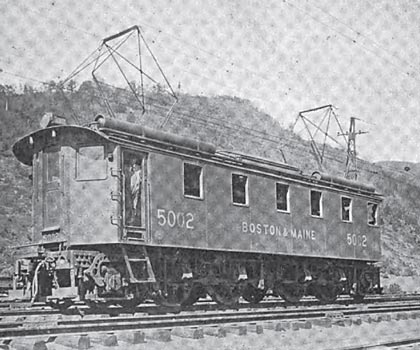
ELECTRIC LOCOMOTIVES
The electric locomotives were built in the Baldwin and Westinghouse shops. Three of the locomotives are intended primarily for freight service, and have a maximum tractive effort of 67,000 pounds and a maximum speed of 30 miles an hour. The others are intended for combination passenger and light freight service, and have a maximum tractive effort of 40,000 pounds, with a maximum speed of 50 miles an hour. These locomotives are identical with the exception of the gear ratio, and by changing the gears and pinions it would be possible to change a passenger locomotive over to a freight or a freight over to a passenger. Each locomotive weighs 130 tons, 96 tons of which are on the drivers, and is 48 feet long between couplers, the total wheel base being 38 feet 6 inches.
The locomotives have two articulated trucks, each truck consisting of two pairs of 63 inch drivers with seven foot rigid wheel base, and a pair of radial pony wheels 42 inches in diameter. The trucks are of very heavy and substantial construction. They carry the draft rigging and are connected together by a heavy draw-bar. The cab is supported by four spring loaded friction plates on each truck. One truck center pin is arranged with longitudinal play relative to the cab, thus relieving the cab of pulling and bumping stresses. The power is supplied by four 375 horse-power single phase motors mounted directly over the driver axles and bolted fast to the frame, thus being entirely spring borne. The power is transmitted from the motor by two flexible gears which divide the load equally and prevent shocks on the gear teeth and also give the motors a chance to start under heavy load. These gears drive a quill surrounding the driver axle with 1.5 inch clearance, and run in bearings in the motor frame. The quill is in turn connected to the wheels by a system of long helical springs which allow the wheel to follow .any inequalities in the track without affecting the motor.
Owing to the short rigid wheel base with the radial lead trucks, the light dead weight per axle, the concentration of weight near the mid length of the locomotive, and the high center of gravity, these locomotives ride very smoothly and are exceptionally easy on the track.
The electrical equipment consists of:
Four 375 horse-power single-phase motors.
One air-blast auto-transformer.
Two 11,000 volt pneumatically operated pantagraph trolleys.
One 11,000 volt oil circuit breaker.
Three preventive coils.
Four groups of pneumatically operated unit switches.
Two 10 horse-power single-phase motors for driving the compressors.
One pilot governor operating a compressor switch.
Two 7.5 horse-power blower motors.
Two 20 volt storage batteries for operating the magnet valves.
One motor-generator set for charging the batteries.
One speed limit relay.
Two master controllers.
Two temperature indicators -for showing the temperature of the main motors.
The necessary control circuits, receptacles and jumpers for multiple unit operation. With the exception of the main motors and storage batteries which are mounted on the trucks and the pantagraphs on the roof, this apparatus is all mounted inside of the cab, and is so arranged as to be visible and easily accessible. The motors are of the series commutator type with short-circuited auxiliary field windings. Twelve taps giving different voltages are brought out from the auto-transformer for acceleration and speed control of the main motors. The overload tripping mechanism of the oil circuit-breaker operates in conjunction with a dash-pot which prevents the circuit breaker from opening as a result of momentary surges in the high-tension line. The circuit-breaker is closed by an air cylinder and opened by a spring and the weight of the moving parts when the control circuit to the magnet valve is broken. This circuit is connected through a removable contact plug in the master controller and a contact disc on the overload trip plunger. The plunger latches open when operated by an overload and can be released only by pressing the reset button on the master controller with the controller handle in the off position.
| |||
| Fig. 12Schematic Wiring Diagram of Locomotive |
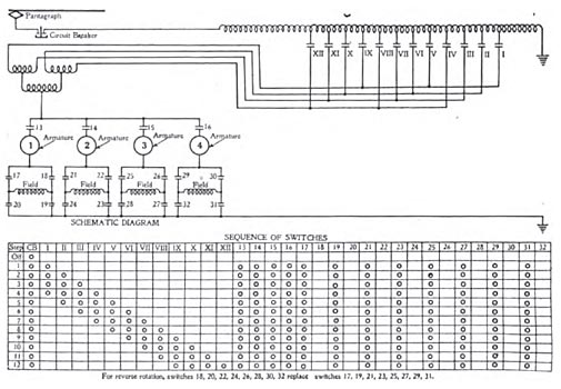
Each of the unit switches in the switch groups is provided with a magnetic blow-out, and is operated by air through a magnet valve and an air cylinder. The main circuit connections and the order in which the switches are closed for acceleration are shown in Fig. 12. The main motors are all connected in parallel, and any motor may be cut out by opening a battery switch in the control circuit to its switches, without affecting the other motors.
An overspeed relay is provided which will automatically disconnect the power lines from the motors at a predetermined maximum speed. This will prevent the locomotives from being accelerated to a speed that will damage the motor armatures, but does not prevent their attaining excessive speed on a down grade. The relay consists of two coils the cores of which are balanced by a rocker arm and carry a contact disc. One coil is energized through a series transformer by the current in a motor lead, and the other by the voltage across the motor armature. The relay disc is normally held away from its contacts by the unbalanced weight on the rocker arm, but when the motor is running at such speed that the coil energized by the voltage across the armature overbalances the coil energized by the decreased current passing through the motor, the relay disc lifts and makes a contact which, through an auxiliary relay, opens the control circuit to the main motor switches.
A very complete shop for the maintenance of the electrical equipment has been built at North Adams. This contains drop pits with hydraulic jacks, well lighted inspection pits, a 15-ton electric crane and machine tools for doing any ordinary repair work.
