The Spokane and Inland Railway
|
[Trade Journal] Publication: Electric Journal Pittsburgh, PA, United States |
||||||||||||||||||
|
THE SPOKANE AND INLAND SINGLE-PHASE RAILWAY
J. B. INGERSOLL Assistant General Manager and Chief Engineer of the Spokane and Inland Railway
THE Spokane and Inland Railway furnishes the first example, large or small, of the use of single-phase railway equipment in the entire Pacific Northwest, and is the second one to begin operation on the Pacific coast, its immediate predecessor being the Vallejo, Benicia and Napa Valley Railway Company, of Southern California.
Beginning at Spokane, Wash., where immediate contact is made with several transcontinental linesthe Great Northern, the Northern Pacific and the Union Pacific systemsthe Spokane and Inland extends in a general southerly direction for a distance of seventy-six miles to the city of Col fax, Wash., which in that direction constitutes the present terminus; at Spring Valley junction, 39 miles from Spokane, a branch line runs to Palouse, Washington, this branch being about 40 miles in length, making the total length of line at present, 116 miles, or 125 miles including sidings. Extensions to one or possibly both of these branches of the "Y" thus formed will no doubt be made in the very near future. The entire field traversed by this electric line is one of great fertility. It is the Palouse country, known especially in the grain market as a great wheat producer, and furthermore destined to develop as a timber producer, since the Washington, Idaho & Montana Railway has built east from Palouse, reaching into one of the largest bodies of white pine timber now standing, and a four band sawmill has been erected at Potlatch, Idaho, eleven miles up the Washington, Idaho & Montana Railway from Palouse. This mill will have an immense capacity, cutting in the neighborhood of a million feet of timber each day, which will mean thirty or more cars of lumber distributed daily to the various transportation companies, the Spokane and Inland handling its share of the tonnage. This wheat, lumber, etc., will make heavy freight. A firm official determination existed on the part of the Spokane and Inland Company from the very beginning to handle this freight electrically, and, according to steam road practice, to employ heavy motive power.
By reason of unfavorable weather conditions, such as heavy snowfall and also because of the extensive trackage, yards, etc., it was not feasible to consider a third rail system, so direct-current considerations were at once reduced to the necessary use of a double No. 0000 overhead trolley paralleled by copper, varying in size from 500,000 to 750,000 circular mils throughout almost the entire system. A lengthy computation was prepared showing the relative advantages of single-phase and direct-current operation. The report submitted to the officials of the road was summarized in about the following manner, the parallel columns showing the relative costs involved by the three-phase, do-cycle rotary converter system and the single-phase, 25-cycle system. These figures apply to a total mileage of 146 of main line, which in actual construction has since been reduced temporarily by thirty miles:
Due to changes made after the contract for the equipment was closed, it is now considered that the saving effected was in the immediate neighborhood of $800,000, representing, at five per cent., an interest of $40,000 per annum, and also a very large percentage of the total cost of the system using direct-current apparatus.
POWER
Practically all of the electric power systems on the Pacific coast are equipped with 60-cycle apparatus. In this respect conditions at Spokane did not differ from the majority of cases and, as it was decided to buy power from an existing power system, the uSE of frequency changers was the only expedient to follow. These were selected in units of 1,000 kw, four sets being required, each set consisting of three separate machines, all mounted on the same base plate, each being of the two bearing, self-contained type with flange coupling between adjacent rotating elements. The 1,000 kw, 25-cycle revolving field, single-phase 2,200 volt generator is coupled at one end to a 1,000 hp, 3-phase, 60-cycle, 4000 volt induction motor operating at full-load speed of 500 r. p. m.; at the other end it is coupled to a 750 hp, shunt-wound 550 volt direct-current machine, which is designed to act as a load balancer for the induction motor, keeping the input to that machine as nearly constant as possible, and as far as the 6o-cycle system is concerned, minimizing the peak loads. The direct-current machine will charge and discharge a storage battery through a booster system, the booster field compensator being actuated from the secondaries of series transformers, placed in the 4000 volt circuit to each induction motor. This is the first system of the sort to be applied to alternating current railroading and offers a new field to the storage battery. The alternating-current power is taken direct from the 4000 volt, 60-cycle generator bus-bars, transmitted two miles to the frequency changing station, and sent out at a potential of 45,000 volts, 25-cycle, single-phase, to the various transformer stations along the right of way. The frequency changing station is a brick, concrete and steel structure of imposing design and together with the 60-cycle power plant, is located inside the city limits of Spokane.
SWITCHBOARD
The switchboard in the frequency changing station consists of 24 panels. All oil switches are mounted separate from the switch-board, each being operated through a system of connecting rods and bell cranks. Graphic recording instruments are placed in the incoming 4,000 volt, 60-cycle circuits and also in the 25-cycle end of the equipment, these furnishing a continuous station log of the power received and the power delivered.
TRANSFORMER STATIONS
For the 116 miles of line, eleven transformer stations are used, consequently the average distance between them is approximately 10 miles. The buildings will be of concrete and brick construction, and will each house the following equipment: 2Low equivalent 45,000 volt lightning arresters, 1Automatic 45,000 volt oil circuit breaker, 2375 kw, 45,000-6,600 volt oil insulated self-cooled transformers. 2Automatic 6,600 volt oil circuit breakers. 16,600 volt lightning arrester. 1Full complement of disconnecting switches for 60,000 and 6,600 volts.
TRANSMISSION LINE
The 45,000 volt single-phase transmission line parallels the track but is separate from the trolley structure. No. 2 hard drawn copper wire is used and is supported on a single cross arm, the wires being spaced 48 inches apart. The insulators are of the three part type, glazed together and tested at 120,000 volts. Metal pins are used of the type made by the Locke Insulator Company. The poles are of Idaho cedar with a minimum top diameter of eight inches, forty feet long and set at an average distance of 100 feet apart on tangents and 50 feet on curves.
TROLLEY LINE
The trolley construction is of standard single catenary, single arm type, for a working potential of 6600 volts. Especial care has been exercised in erecting this line and material has been used unsparingly, the result being that an excellent example of high class work is here afforded. It has been put up to stay. The poles are of well selected Idaho cedar, 40 feet long with a minimum top diameter of eight inches and are set six feet in the ground. Many holes had to be blasted out of the solid rock. A large percentage of the poles are guyed securely and especially so on curves. The trolley wire is 22 feet above the head of the rail.
LOCOMOTIVES
Six locomotives are being supplied, each weighing approximately 50 tons, of the double truck type, equipped with four 150 hp, .single-phase railway motors, having a normal voltage of 225 volts. The dimensions of the locomotives are as follows: Height from head of rail to top of cab, 11 feet, 9 inches. Width over all, 9 feet, 6 inches. Length over bumpers, 32 feet, 6 inches. Rigid wheel base, 7 feet, 4 inches. Wheels, 38 inches diameter. Distance between truck centers, 13 feet, 9 inches. All locomotives are double end, fitted with straight and automatic air brakes, and electro-pneumatic multiple-unit alternating current and direct-current control, and have duplicate motor-driven air compressors. Most of the control and brake equipment will be inside of the cab in a very accessible position, facilitating ready inspection of parts and quick repairs. Two auto-transformers of the.oil insulated self-cooling type are supplied for each locomotive, having a combined capacity sufficient to supply the motors with power tinder heavy overload conditions. These are also placed inside the cab. Each locomotive is intended to haul seven 45-ton cars on a level track at 30 miles per hour and ten such cars on a level at 25 miles per hour. When coupled in tandem, the weights back of the drawbars may be doubled. It is proposed to use double-headers in regular service and to do practically all of the heavy freight work at night, thereby keeping the load-factor of the system as high as possible.
PASSENGER CAR EQUIPMENT
Standard passenger trains consist of three coaches, two with motors and one without motors. The two motor cars are run in front, leaving the third car as a trailer. The electrical equipment for each motor car consists of four 100 hp, single-phase motors, complete with both alternating-current and direct-current multiple unit pneumatic control and one auto-transformer of the oil insulated self-cooling type. The trolleys for alternating-current service are of the pneumatically operated pantograph type. Wheel trolleys with bases insulated for 6600 volts are also supplied, an oil type emergency switch being used for interconnection between the trolleys in case of failure of one or the other. Each motor car with load weighs complete approximately 42 tons, the trailer 31 tons, making a three car train weigh approximately 115 tons total. The car wheels are 36 inches in diameter, which with a gear ratio of 20:63 gives a speed of 45 miles per hour, on a level track.
A two car train made up of a motor car and trailer, of a total weight with load of 73 tons, has a maximum speed of 50 miles per hour on the level and a schedule speed of 36 miles per hour on a four mile run. All equipments, including the locomotives, are designed to work on standard 600 volt direct-current trolley lines when desired, as all trains entering the terminal station in Spokane use direct-current. At present 15 quadruple equipments of 100 hp motors have been ordered for passenger trains. Six motor cars will be the combination passenger and baggage type, 59 feet in length, all single end control. Five cars will be of the straight passenger type, 56 feet, 6 inches long, all single end control. One motor car of the straight passenger class will be double end control and will be used for service. There will also be three 58 foot observation cars without motors. Car bodies and trucks for the remaining three complete motor equipments have not yet been ordered.
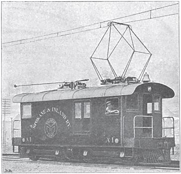
FREIGHT MOTOR CARS
For light freight and express service, there are six quadruple. 100 hp equipments, these being the same as those used on passenger service, except that the gear ratio is lower and all are of the double end type in both electric control and brake equipment, both straight and automatic brakes being used. The air compressors are in duplicate. The car bodies are of the box type 50 feet long over the bumpers. Besides having a large freight carrying capacity, they will be used as light weight locomotives and will be capable of hauling two 45 ton cars on the level at 45 miles per hour. Heavier trains can be handled if desired on shorter runs without overheating the equipment. These lighter locomotives may be run tandem or multiple, making them valuable auxiliaries to the heavier locomotives during periods of congested freight traffic.
|