North Mountain Power Co's. Hydro-Electric Plant
|
[Trade Journal] Publication: Electrical World New York, NY, United States |
||||||||||||||||||||
|
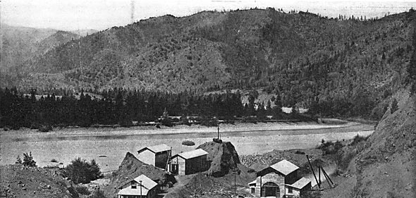
North Mountain Power Company's Hydro-Electric Plant. Among the power transmission systems of the Pacific Coast, that have been constructed with an eye to the future, rather than the present needs of the communities which they serve, is that of the North Mountain Power Company. This plant is located in the central part of Trinity County, California, two miles below the town of Junction City, where Canon Creek, from which the water used for power is obtained, flows into the Trinity River. Weaverville, the county seat, is twelve miles distant by road. The nearest railroad point is Redding on the "Shasta Route" of the Southern Pacific R. R., Humboldt Bay, on the Pacific Ocean, while Eureka, the chief coast city of northern California, lies in an almost due westerly direction at a distance of 59 miles in a straight line. The altitude of the plant is about 1,400 ft. All material, cement and machinery were hauled in over 6o miles of the severest mountain roads, across three distinct divides or summits, viz.: Trinity Mt., Brown's Mt., and Oregon Mt. It required 18 to 20 animals to pull each of the larger pieces, weighing 18,000 lbs., up the grades, and when mud was encountered it was necessary to hitch 18 animals to the fall of a block and tackle fitted with steel cables. Despite these difficulties, however, no mishap occurred to any of the machinery.
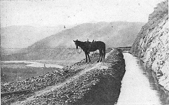
The water used at the plant is diverted from Canon Creek, which has a drainage area of 52 sq. miles above the diverting dam. The upper part of the basin is a rugged, glaciated granite country, extending up to an altitude of from 9,000 to 10,000 ft. above sea level, where some snow remains throughout the year. The higher parts of this basin are in the nature of an immense amphitheater, lying on a flank of a peak, which is a characteristic feature of all elevated glaciated topography. And, as is so often the case, the converging and descending glaciers have scooped out immense holes with almost perpendicular sides, which now form the beds of two lakes. These lakes have been pressed into service as storage reservoirs. Part of the watershed is heavily timbered, and lies within the boundaries of a government forest reserve. This will insure the preservation of the forests, which are so effective in steadying the run-off. The average rainfall for the last thirty-three years at Weaverville, twelve miles from the plant, has been 42.50 in. At the higher levels of the watershed the precipitation is much greater, but no records are available for that region because the country is absolutely uninhabited, and without even trails, except for the one to the above-mentioned lakes, which now form the storage reservoir for the North Mountain Power Company. The dam is small and serves merely for diverting the water. It is of the usual rock-filled crib form, which type has been used for many years in mining operations on the Pacific Coast. The ditch system consists of alternating sections of ditch, flumes, and one tunnel. Part of the ditch is cut in solid rock, but the most of it is dug in the side-hill soil, which stands well and puddles well. The flumes are 19 in number and vary in length from 30 to 1,200 ft. Those immediately below the dam are laid upon a solid bed-rock bench, and are equipped with adequate spill-ways, waste-gates and sand boxes. The total length of the flumes is 5,250 ft., almost exactly one mile. A tunnel 1,821 ft. long has been driven to replace a temporary flume which was unavoidably built upon treacherous sliding ground. This tunnel is heavily timbered throughout its entire length, and tightly lagged except where the rock is unusually hard. The dimensions of the main tunnel are 4 ft. 9 in. by 5 ft. to in. in the clear. The total length of the ditch, flumes and tunnel is 7 1/4 miles. The average grade of all is 9.73 ft. per mile. The ditch is provided with waste gates and sand boxes at suitable locations. The capacity of the ditch is 80 cubic feet per second, which is sufficient to operate at full load three-units like the two which are now installed. Near its lower end the ditch passes through a gap in the narrow ridge separating Canon Creek from Trinity River, and terminates in a forebay on the river side of the divide. Thus is secured a head due not only to the fall in Canon Creek in the seven miles through which the Creek and ditch parallel each other, but also to the additional fall in a further course of two miles to the Creek's junction with the Trinity River, and to the added fall in two miles of the river's course between the junction and the plant. A telephone line extends from the power house along the entire course of the ditch to the head dam. Instruments are placed in the station, the forebay tender's cabin, the head-gate tender's house, and at several other points along the line. Portable telephones can be readily connected at any point, and, as a result, any place along the ditch can have prompt communication with the power house.
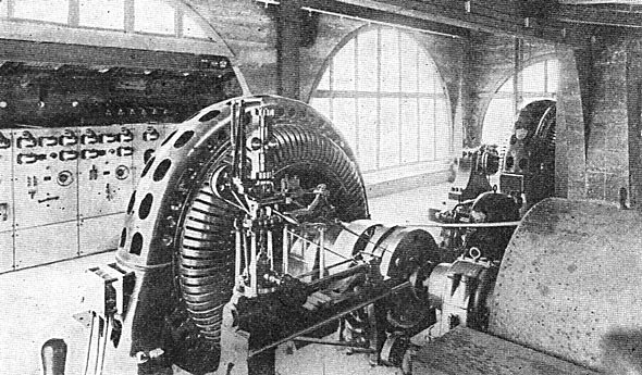
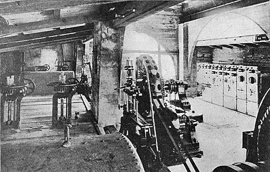
The forebay is excavated out of the solid rock of the hillside, 10 ft. deep, 14 ft. wide and 60 ft. long. The ditch is provided with a gate at its entrance to the forebay, and the latter contains a gate and grizzley at the intake of each of the two penstocks. Provision has been made for a third penstock when a third unit shall become necessary in the plant. Suitable trash-racks are provided just above the forebay. Each penstock is 1,165 ft. long. Under a total head of 604 ft. there is an effective head of 604 ft., giving a working pressure of 260 lbs. per square inch. There is one complete independent penstock for each of the two units. Each penstock consists of a line of 36-in. and 28-in. pipe, and at the lower end two lines of 18-in. all riveted steel pipe of various gauges according to its position in the line. At the points where the single 28-in. pipe branches into two 18-in. lines, the penstocks are enclosed and anchored in a massive block of masonry laid up with imported Portland cement mortar. At their lower ends just before entering the power house they are secured by a similar form of construction, and at various points they are held by bands and anchor bolts leaded and sulphured into the bed-rock. Throughout their entire length they are laid in trenches and covered by back filling, except at their lower ends where the profile of the hill is such that it was best to lay each in a separate tunnel. After completing and testing the penstocks, the tunnels were wailed up and back-filled. Each penstock is provided with an 18-in. standpipe just outside the forebay walls to allow air to enter when the forebay gates are closed, and thus prevent collapse of the pipe. The penstocks are also provided with air-valves and manholes at suitable points. The plant proper consists of the power house, the transformer house and the high-tension switch house. In addition, there are the shop, the operator's dwelling and the stable. At the forebay is the forebay tender's cabin, and at the dam is a house for the tender of the head gates. Each of the two hydraulic units consists of a pair of 44-in. Pelton wheels under one sheet-steel housing, provided with ring-oiling, self-aligning bearings, coupled to the generator through flexible leather-link couplings. The nozzles are of the deflecting type. With the largest tips in service the wheels are capable of driving the generators at 25 per cent overload. The wheels are controlled by type "F" Lombard- governors using oil. The pressure and vacuum are maintained by oil pumps belt-driven from the wheel shafts. The governors are not fitted with any form of switchboard speed control mechanism, but a single operator has no difficulty in synchronizing a generator under the load conditions which exist in the plant. The tail race is 6 1/2 ft. wide and excavated for 280 ft. through bed-rock to the Trinity River. The generators, two in number, are of the Bullock type, furnished by Allis-Chalmers Company, of Milwaukee. Each is a 750-kw, revolving-field, three-phase machine' designed for 500 r.p.m., 2,200 volts, 25 cycles. Two Bullock 45-kw, 125-volt exciting dynamos are driven by belts from the generators. The switchboards are of marble and have Wagner instruments.
The power house, 36x51 ft., is built of concrete made up with sand and gravel, taken from the river bars a few rods from the site of the plant, and with imported Portland cement. A special bay or alcove has been provided to give ample space behind the switchboard. The roof is of corrugated iron supported on steel trusses. A "Cyclops" hand-operated crane spans the main part of the building, and is fitted with a 2,000-lb. "Triplex" block. This easily handles the heaviest piece of machinery. The leads between the generators, exciters and switchboard are lead-covered cables laid in conduits within the concrete and cement floor.
The transformer house is 13 ft by 51.5 ft. in outside dimensions, and is also built of concrete. It is 50 ft. distance from the power house. It contains seven step-up transformers, viz.: two banks of three each and one in reserve. They are of Bullock make, 300-kw, water-cooled, oil-insulated, 2,200 to 19,050 volts. Each bank is located in a separate room, and the seventh or spare transformer is in a third room. They stand upon rollers which in turn rest upon tee rails set into concrete piers. The spaces between the piers are filled with gravel and, provided with sub-drainage so as to allow any-oil rapidly to escape in case of leakage or accident. The water piping is connected up with unions and so arranged that every transformer is interchangeable with every other one, as far as water and electric connections are concerned. A track runs the entire length of the building and at such an elevation that the floor of a car is at the same height as the rails which are imbedded in the concrete piers. Thus any transformer can be quickly rolled out upon the car, removed, and another reconnected in its place with the minimum of delay in case of accident. Each penstock is tapped in the power house, and after passing through shut-off and throttling valves under the control of the operator, water is delivered into a cylindrical steel tank, 36 in. diameter by 24 ft. long. This storage tank is set upon a little knoll about 20 ft. above the level of the transformers. From this tank the water circulates through the cooling, coils of the transformers by gravity. The transformers are connected in delta on the low-voltage side, and in star on the high-voltage side, giving a line pressure of 30,000 volts. The high-tension switch house is 16x36 ft. in outside dimensions; a frame structure covered with corrugated iron; 20 ft. distant from the transformer house. In it are two banks of "M-T" single-throw air-brake switches, and G. E. alternating-current multiplex lightning arresters, connected up for the three-phase circuit. The pole-line extends almost due west from the plant to the sub-station in Eureka. The length is 65 miles. Fifty-five miles of the route are over a severely rugged mountainous country; the altitude of the plant is only 1,480 ft. and Eureka is at sea-level, but the line passes over several summits ranging from 4,500 to 5,500 ft. in altitude. Fifty miles of its length lie in a heavily timbered country, requiring a tremendous amount of clearing, the trees ranging from 2 ft. to 4 ft. in diameter. It was necessary to construct a trail over nearly the entire length of the line. The route deviates from a straight line only slightly and only where the topography made it unavoidable. It is a "thorough" transmission, so to speak, there being no taps on the line anywhere between the plant and the sub-station at Eureka. The line is a single three-phase circuit. Each conductor is a No. 4 copper wire, except on some long spans where stranded cable is used. There are about 35 poles to the mile. The poles are redwood at the western end; in the inaccessible stretches the native red fir was the only wood available. Insulators are Locke two-piece single-petticoat porcelain, 8.5 in. in diameter. In the fog-belt a larger insulator of a similar design is used. Pins are of sun-dried eucalyptus, oiled, 1.5 in. in diameter. The spread of wires on the standard length spans is 40 in. The length of spans varies from 50 to 100 ft. according to the conditions and topography of the country. The telephone circuit is No. 10 B.B. galvanized wire, carried on glass petticoat insulators. Telephones (Stromberg-Carlson) are connected to the line at several of the cabins which have been built for the accommodation of the patrolmen, and at frequent intervals are "pole-boxes" consisting of magneto-generator and batteries into which the patrolmen plug their pocket sets and thus have long-distance loud-talking instruments. The sub-station at Eureka includes an auxiliary steam plant as follows: Two B. & W. water-tube boilers fitted with Peabody patent oil burning furnaces, duplicate oil pumping system; Goubert auxiliary feed-water heater; Wheeler "Admiralty" surface condenser with self-contained steam-driven air and circulating pumps, cooling water being taken from Humboldt Bay, and a McIntosh and Seymour tandem-compound engine of nominal rating of 700 hp. A jackshaft running at 500 r.p.m. is connected to engine by rope-drive. A Bullock 500-kw, 550-volt rotary converter is arranged for direct connection to this jackshaft by a jaw clutch and so driven by the engine. This arrangement permits of carrying the load by steam when necessary to shut down the transmission line for repairs. The clutch has a synchronism indicator in the nature of a lamp, so that the engine may be connected to the rotary while it is running at full speed on the power transmitted from the Trinity River plant. For the rotary converter there are three Bullock 150-kw, water-cooled transformers. For the local distributing system are three G. E. 400-kw, water-cooled transformers. For furnishing power to the 60-cycle incandescent and arc lighting circuits of the city of Eureka, a three-phase, 60-cycle generator is driven by the rotary acting as a synchronous motor. A fuel oil tank 54 ft. in diameter by 25 ft. deep holding 10,000 barrels has been built near the sub-station, and is connected to a dock on Humboldt Bay by a pipe-line. The load at present consists chiefly of lights in the city of Eureka. Some motors are already connected to the circuits, and the motor load is being rapidly developed. Local transmission lines are being constructed about the shores of Humboldt Bay, and in a very short time the company will be supplying power to the local companies in Eureka's suburbs, not only for lamps but for motors to the various industries of that rapidly developing region.
|