50,000-Volt Transmission at Brusio, Switzerland I
|
[Trade Journal] Publication: Electrical Review New York, NY, United States |
|||||||||||||||||||||||||||||||||||
|
The Brusio Hydroelectric Plant and Its 50,000-Volt Swiss-Italian Transmission System. By Frank Koester.
THE largest and most recent hydroelectric installation in continental Europe is that at Brusio in the southeastern corner of Switzerland. Some 3,155 feet above sea level, bordered by the slopes of the Bernina Mountains, lies the lake of Poschiavo. This lake receives, among others; the waters of the River Poschiavino and its tributaries as well as those of the River Cavagliasco, which in turn collects the waters of the glaciers Cambrena and Palu. The total drainage area which feeds, this lake is seventy-seven square miles. The area of the lake is 0.77 square mile and its greatest depth is 260 feet.
Owing to the high altitude of the lake the water Supply. in the winter time will be considerably less than during other seasons, consequently the equipment of the plant with proper regulating devices became very essential. Therefore one of the foremost requirements consisted in damming the lake at its outlet, where the River Poschiavino continues, so that the water level of the lake may be raised 3.3 feet above the normal and lowered by siphoning as much as 24.3 feet below the normal level, thus providing a natural reservoir giving a reserve water supply of 520,000,000 cubic feet.
The headrace leading from the lake is carried to Monte Scala, a distance of 3.25 miles, by a tunnel through the Mountain at a considerable depth, where a collecting basin is provided. The power plant is located at Campocologna, receiving the water through penstocks from the collecting basin under a head of 1,300 feet.
Current is generated at 7,000 volts and is transmitted through a tunnel across the boundary into Italy, where, at a substation in Piattamala, the voltage is stepped up to 50,000 for use by the Societa Lombarda, an Italian distributing company, to work in parallel with their well-known stations in Vizzola and Castellanza. This company guarantees the use of 16,000 kilo-watts. From the power plant itself several aerial lines transmit current to various other consumers in Switzerland, and among them it will assist a small power plant still under construction at Sajento. The 40,000-volt transmission line, from Piattamala to the substation at Lomazzo, is 88.5 miles in length and consists of two independent lines. A 20,000-volt transmission line branches off northward to Como from the station at Lomazzo, running a distance of thirty miles. An 11,000-volt line runs southward eight and one-half miles to the steam-power plant at Castellanza for assisting or drawing current from same. The bulk of the current is used for spinning and weaving mills, which begin operations at 7 A.M.; reaching its maximum in a half hour, the load remains steady up to 12 o'clock noon, dropping in thirty minutes to a few hundred kilowatts and again reaching its maximum at 1 P.M., where it remains up to 7 P. M. During the night only 2,000 kilowatts are necessary. The entire hydroelectric development and transmission system is considered the most up-to-date in Europe, embodying many excellent examples of modern European practice.
SIPHON SYSTEM.
As the level of the water in the lake will vary in the neighborhood of thirty feet, the headrace tunnel is located 32.8 feet below the normal water level. It was not advisable to connect the tunnel directly with the bed of the lake, therefore a siphon was installed. For this purpose a shaft was sunk about seventy-five feet from the water's edge and carried 7.4 feet below the low-water level. The shaft is twelve feet in diameter and the portion below water-level was built under air pressure. From this shaft the headrace or supply tunnel, having a diameter of 8.9 feet at this point, leads to the collecting basin.
The lake is connected to this shaft by means of a siphon tube 6.5 feet in diameter and 270 feet horizontal length or body. The suction leg is twenty-six feet long, provided with a screen and butterfly valve, while the discharge leg is 27.7 feet long. The latter is provided at its bottom end with a disc valve for regulating the flow of water. The tube has a pitch of five feet in a thousand and is provided at its highest point with nozzles; one being three and one-half inches in diameter connected to a double-stage air-pump for starting the siphon, and the other, an eight-inch connection for a centrifugal pump which is used for cleaning the siphon tube and particularly the screen. Instead of using the air-pump for starting, the centrifugal pump may be called upon, in which case, both butterfly and disc valve are first closed. Fig. 1 shows the general arrangement.
Since about 180 feet of the horizontal length of the siphon is located in the lake under the normal water level, this portion of the tube, made in sections of thirty-six feet, was fitted at its ends with blank flanges and then floated to its position between piles and anchored to the frame-work of the piling. The final flange connections were made by divers.
SECONDARY WATER SUPPLY.
For the purpose of damming the water in the lake six sluice gates were built at the outlet of the lake, five of these gates being 13.12 feet wide and one being 6.56 feet wide. The smaller one, which is located lower than the others, is used for passing sand and gravel. Located at a right angle to the dam or sluice gates, is a small basin provided with a screen. A thirty-three-inch pipe, provided with a gate, leads from this basin to the headrace tunnel, 800 feet below, where a shaft was sunk to receive the pipe; this arrangement, constituting a secondary water supply, was utilized in order to start up, the plant at an early date. The size of this pipe was chosen so that it might later be used as one of the penstocks leading from the collecting basin to the powerhouse. This pipe by-passes the upper section of the headrace tunnel and the siphon system, furnishing the water supply during their construction pending the securing of necessary concessions.
HEADRACE.
The headrace is 17,056 feet long, 4,920 feet running through moraine (a formation similar to landslides) and the remainder through gneiss. A portion of the tunnel, near the collecting basin, lies about 100 feet deep, while the greatest portion of its length lies some 425 feet beneath the surface. With that portion of the tunnel lying at the greatest depth and running through the gneiss formation, no difficulty was experienced from seepage and air leakage, while in the portion nearest the surface, and where the tunnel runs through moraine, such difficulty was experienced. For the purpose of draining the seepage water and discharging the air, eleven lateral tunnels were cut having their outlet at the nearest point on the mountain slope. The tunnel, where cut through the rock, was lined with concrete to a point above the water line, while the portion of the tunnel above the water was left unlined Where the tunnel runs through the loose earth (moraine) it is constructed partly of concrete and partly of reinforced concrete, and where it was cut through the rock, pneumatic drills running on tracks were employed. For this purpose, and for lighting, a temporary power plant was installed, utilizing the fall of the Sajento River. The headrace was constructed of a wooden flume 910 feet long and a twelve-inch steel penstock. A fifty-horsepower turbo-generator, giving 4,000 volts, and the turbine also operated a two-step compressor supplying air at ninety pounds pressure through two main pipe-lines. At three of the seepage discharge tunnels ventilators were installed during construction, while at the remainder ventilation was produced by means of branches from the compressed-air lines. Leading to the mouths of the seepage discharge tunnels Nos. 6 and 9, 1,000 to 1,500 feet above the valley, were electrical cable transportation lines. At seepage discharge tunnel No. 2, near the lake, an overflow system is provided with a sand and gravel trap. The entire tunnel, which, is egg-shaped with a flat bottom, has a slope of two feet to the thousand and has a sectional area of fifty-three and one-half square feet. The average velocity of the water in the tunnel when partly filled is 6.5 feet per second. Should the possibility arise that in the future the tunnel should be used as a pressure tunnel, for which provision has been made, the velocity of the water will be five feet per second.
As will be noted from the dimensions of the tunnel given above, the volume of water contained in same furnishes auxiliary storage capacity to the collecting basin. Furthermore, for a length of one mile the sectional area of the tunnel was increased, and in order to properly regulate the water supply to the collecting basin, an additional overflow was provided at the seepage discharge tunnel No. 9, discharging into the above-mentioned Sajento River. The collecting basin is so dimensioned that with average loads the level of the water will be constant, while with light loads the level of the water will be higher, and during the hours of maximum load the water level will be correspondingly lower.
COLLECTING BASIN AND PENSTOCKS.
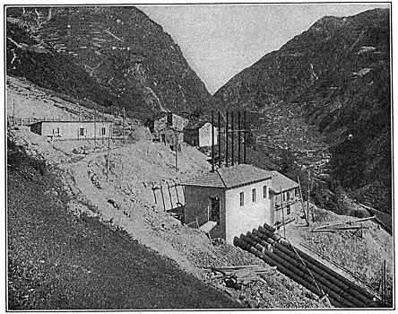
The collecting basin is located 1,300 feet above the valley and is provided with six penstock connections arranged in pairs. The connections of each pair are located in separate chambers provided with screens. The usual practice of providing the penstocks with cutoff gates has not been followed owing to the sudden rise and fall of the water. An automatic float arrangement for signaling the attendant was installed, operating by releasing a pawl and a magnet clutch and allowing a swing gate to close. About 100 feet from the collecting basin is a gate-house through which pass the six penstocks. At the headgates they have a diameter of 33.5 inches and, owing to the high head (1,380 feet), considerable material was saved by reducing the diameter at the power-house to 23.5 inches by telescoping certain sections of the penstocks, thus giving at its lower end a velocity of 11.5 feet per second. The penstocks are made up of rolled steel in sections 39.36 feet in length. The heaviest material employed is seven-eighths inch. The sections are bolted together by the use of movable flanges. As will be seen in Fig. 2, the penstocks run down the mountain slope at various angles, at which they are anchored in solid concrete blocks, there being ten anchorages. Between these anchorages the penstocks rest on concrete piers, the expansion being provided for by the use of slip expansion joints. At the headgates (Fig. 4) each penstock is provided with a vent pipe about forty-five feet high. Drainage gates are provided at the lower ends of the penstocks for draining into the tailrace. Here the six penstocks are interconnected by a cross pipe having two outlets, one leading to the exciters, and the other being provided with a safety device, so that in case of excess, of pressure the "bursting plate" gives way and relieves the penstocks. This cross-pipe connection also serves the purpose of maintaining a uniform circulation. There are at present installed, corresponding to the main turbo-units, five penstocks. For hoisting the penstocks and other materials during construction, an electrically operated cable road was installed. The drum and motor are located in an annex to the gate-house near the collecting basin.
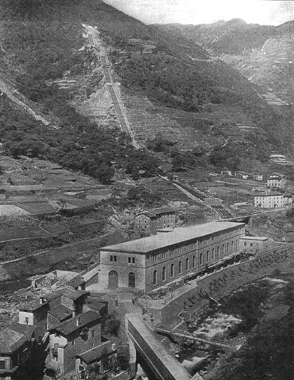
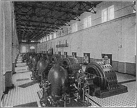
POWER-HOUSE.
The power-house (Fig. 2 and Fig. 3) is located at Campocologna alongside the River Poschiavino. The main generator room is 342 feet long by 56.4 feet wide. At the side there is a. single-story switch annex 311.5 feet long by 10.75 feet wide, with a three-story central section for offices. Owing to the topography heavy retaining walls were required, with deep and expensive building foundations. Up to the main generating-room floor the building is of-concrete, while the superstructure is of quarried stone and tile. The roof construction is expensive and is as follows: Between I-beam purlins are large tile blocks, the undersides of which are glazed to form a finished ceiling. These are covered with a one-eighth-inch layer of cement over which are spread three layers of so-called wood-cement (consisting of sawdust and cement), between each of which is laid a layer of paper. Above the layers of wood-cement are reinforced concrete slabs, an air space of two and three-eighths inches being left between these slabs and the wood-cement. These precautions have been taken on account of the extreme heat in the summer time. The building accommodates twelve turbo-generator units, each of 3,000 to 3,500 kilowatts' capacity, and four exciter units of 250 horse-power each. Ten of the turbo-generator units are at present installed. A twenty-five-ton electrically operated traveling crane serves the entire generating room.
TURBO-GENERATOR UNITS.
There are two different types of turbines installed: The Pelton wheel of Escher, Wyss & Company, of which there are at present four installed, two main and two exciter turbines, and the Girard turbine with partial admission, of Piccard, Pictet & Company, of which there are at present installed four main and two exciter turbines. The main turbines (3,000 kilowatts) run at a speed of 375 revolutions per minute and the exciters. (150 kilowatts) at 430 revolutions per minute. The turbines are direct-connected to the water-wheels by flexible insulated couplings of the Zodel-Voith type. The generators are 3,000-kilowatt, three-phase, fifty-cycle, 7,000-volt machines, and are designed for an overload capacity of twenty-five per cent. They are of the sixteen-pole, revolving field type. The poles are cast directly to the field ring. The stator is made in halves and has a bore of ten feet two inches, the width being three feet seven inches. The bedplate is made in two sections with the bearings cast on. The Elektrizitats Gesellschaft Alioth, Miinchenstein-Basel, Switzerland, manufacturers of the generators, who installed also the entire electrical equipment, guarantee the efficiencies as follows:
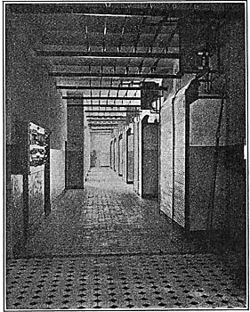
The four exciters are of the six-pole, 115-volt, shunt-wound type. They develop 150 kilowatts at 430 revolutions per minute. Each exciter serves four generators with twenty-five per cent overload. Contrary to the usual practice of centralizing the switchgear, because it was thought best for the convenience of operation and a material decrease in first cost and simplification of the wiring system, each generator has its own switchboard. As will be seen in Fig. 5, these switch-boards are located against the wall next to the switchroom and directly opposite each generator.
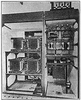
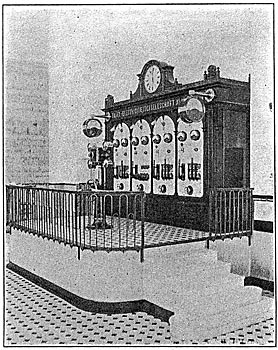
+Thus the station is divided into complete unit systems. However, to control all switchboards from one central point an instrument column has been installed as will be seen later on. The switchboards are of ornamental design and are faced with white marble slabs. All high-tension parts of the switchgear are located on the opposite side of the wall (Fig. 6 and Fig. 7) in masonry compartments fitted with corrugated-iron rolling shutters. Each generator switchboard is - equipped with the following instruments: Two voltmeters; one synchroscope, with phase lamps; three ammeters, one for each phase; one three-pole oil switch, which may be operated by hand or automatically. There are, further, an ammeter on the central column, a main-current rheostat for excitation, and a field-discharge resistance. Owing to the non-centralization of the switchgear system it was not considered necessary to install a double bus4mr or ring system so common in Swiss practice. Fig. 8 represents the wiring diagram and it will be noted that there is one main and one exciter bus-bar system. Both systems are divided in the middle by sectionalizing switches. It will be further noted that the three generators at the left, which may also be independently excited, may be thrown upon a separate bus-bar group. The current from these three generators is intended for the Valley of Brusio and for the operation of the Bernina Railway. The outgoing feeders, with the exception of those just mentioned, are connected at the middle of the bus-bars, which are made up of copper strips two inches by three-sixteenths inch, the area of each strip being sufficient for one generator. Thus, where each generator connection joins the bus-bar an additional layer has been added. The bus-bars run the entire length of the switchroom, above the aisle and close to the ceiling. They are carried on petticoat insulators fastened to I beams and are securely anchored in the middle and at the ends, so that in case of a severe short-circuit the different phases will not be thrown together. The exciter switchboard (Fig. 9) is located upon a platform in the middle of the generator room opposite the exciters. It is provided with four white marble panels, one for each exciter, and upon each of which are mounted a voltmeter, ammeter, knife switch, shunt rheostat and a Reversite circuit-breaker. In front of the exciter switchboard is the above-mentioned central instrument column upon which are mounted the following instruments: An ammeter, with multiple-throw switch, to read the current of each generator; one voltmeter, with plugs, for each phase; two ammeters, one for each of the outgoing feeder-systems of the Societa Lombarda, and one hand wheel operating a shaft to which are connected the shunt rheostats of the four exciters. From this column one attendant may control the operation of the entire plant.
|