Hewlett Insulators
|
[Trade Journal] Publication: General Electric Review Schenectady, NY, United States |
|||||||||||||||||||||||
|
INSULATORS FOR HIGH VOLTAGE TRANSMISSION LINES By E. B. MERRIAM
The insulation and mechanical construction of a high tension transmission line constitute a problem which has been given a great deal of thought by electrical engineers, these being limiting factors of the voltage at which power can be transmitted. To those familiar with the mechanical construction and the insulation afforded by a pin insulator such as is used on high tension transmission lines at the present day, it is quite evident that there are strains present which are both mechanically and electrically objectionable. The problems presented in designing an insulator of this type which shall be of reasonable size, and at the same time properly insulate, suspend and anchor the line, are numerous, and as a result a new form of insulator became necessary.
To meet these requirements a new type of insulator has been designed and is being manufactured by the General Electric Company. There are two forms; one a "link suspension" insulator, (Figure 1), and the other a "link strain" insulator, (Figure 2).
The insulator consists of a solid porcelain piece, having a flanged rim which affords a long creepage surface between live parts, and insures at least some portion of the surface being sheltered from rain. There are two interlinked holes in the center, (Figure 3), through which the cables or guy wires are threaded, thereby bringing a compression strain on the porcelain. The use of cement has been avoided, the entire unit being made from one solid piece of porcelain. It is called "link insulator" because the two guy wires are linked about the porcelain insulation in such a way as to prevent the line falling, even though the insulator be cracked. (Figure 4). An insulator 10 inches in diameter has been found to be suitable for a working strain of 25,000 volts, and a 6-1/2 inch disc for 12,000 volts. The insulation for higher voltages is obtained by installing several of these units in series, an arrangement which might be termed a "series unit" system. Insulators are spaced at a distance between centers approximately equal to the diameter of the insulator.
There are several schemes under consideration for fastening the insulators together, that of threading a single steel strand through the holes until the desired strength is obtained, being the most promising (see Figures 1 and 2). Other methods which give more or less promise, consist of a loop with bolt; stranded cable, either tied or spliced; cable with special sleeves, etc., but practice will dictate the means most desirable.
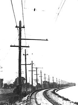
The same general design of insulator is used for high tension trolley construction, and permits of many desirable arrangements for this class of work. It is especially good on 6600 volt catenary construction, and has been used with great success. With this construction a more substantial and lasting installation is obtained than that afforded by the use of treated wood or compound. The insulator can be located some distance from the trolley wire, which reduces the liability of its being broken by a blow from the trolley wheel, (Figure 5). It is evident that single units can be used for insulating suspensions, anchors, pull-offs, and a number of other structural details. This type of insulator has been subjected to exhaustive tests by frost, water, smoke and heat, together with mechanical and electrical tests of almost every description, with very satisfactory results.
When discussing the number of insulators required in series, the question naturally arises as to the voltage distribution per unit. Tests show that the voltage necessary to arc over a series of units is in direct proportion to their number. Under operating conditions, the potential distribution across the series is, of course, not uniform: the insulator nearest the line being subjected to the greatest strain; the worst condition being when the line is grounded. Under this condition, the distribution across the three 10 inch insulators, on a 75,000 volt system, will be 43%, 27% and 30% of the line voltage, the insulators being six feet from ground. The maximum voltage per unit in this case is 32,000 volts, or less than 40% of the dry arc over value. It will be seen that the factor of safety is large, when it is remembered that these 10 inch discs are subjected to a dry test of 3-1/2 times the normal voltage rating, and will withstand a wet test of twice that voltage. When the insulator is wet the potential distribution is evened up by the film of moisture on the outside, and the strain per insulator is approximately the same. Consequently, the question of voltage distribution is not serious, and no trouble should be expected from this source. It is very interesting to note that as the potential is increased the distribution becomes better, and as we approach the arc over point, it is the same for each insulator. The voltage distribution is further influenced by the distance from ground, the greater the distance the better it becomes.
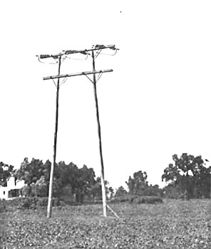
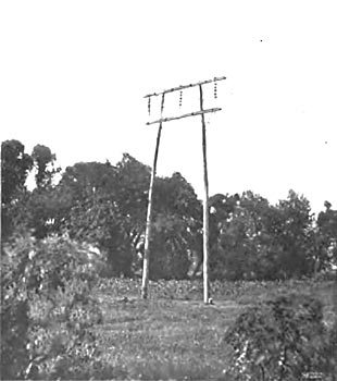
Figures 6 and 7 show two experimental transmission towers equipped with link suspension and link strain insulators. The link strain insulators serve to insulate and anchor the line at intervals, while the link suspension insulators insulate and suspend the line on the intermediate towers. From observation on this experimental line, apparently no trouble should be expected from swinging or vibration, a group of insulators swaying as a single unit.
These towers were 800 feet apart, and in a certain high wind storm the cables all kept their relative positions, and were deflected, rather than swung, by the wind. There is very little vibration due to the flexible connections, and almost no longitudinal waves. The particular advantages of this form of insulator are many and may be enumerated as follows: The material is subjected only to compression strains. The line construction avoids torsional strains on the cross arm. Direct pull from the tower, permitting longer spans and necessitating fewer insulators on turns. A higher electrical and mechanical factor of safety than that obtained by any other known method. The transmission voltage is limited by the number of insulators in series. Simplicity of line construction. Manufacture is simplified by having one type of insulator. The tower being the highest point in the construction, the line is less liable to damage by lightning. This design will prevent the line falling away from the tower, even though the insulators be destroyed. The cost increases directly with the voltage, while it might be said that the cost of the pin insulator, for high voltages, increases as the cube of the voltage. The suspension being flexible, this minimizes the liability of fatigue in the conductor, which might occur with a rigid support.
|