[Trade Journal]
Publication: Electrical World
New York, NY, United States
vol. 48, no. 24, p. 1147-1149, col. 1-2
The Hydro-Electric Plant of the Belton Power Company.
By GEORGE WRIGLEY.
THE generating plant of the Belton Power Company is located on the Saluda River, at a point about seven miles east of the town of Belton, S. C. The river, at the location of the plant, encounters a series of rapids, arid the hydraulic development adopted utilizes to the best advantage the fall due to these rapids.
The Saluda River, one of the tributaries of the Congaree, rises in the foothills of the Appalachian Mountains and drains a basin of approximately 534 square miles above the Belton dam. The absolute low water flow of the river was found to be 270 cu. ft. per second at the plant site. The normal flow does not, however, run lower than 600 cu. ft. per second for go per cent of the time. As the principal users of the power are cotton mills, operating for eleven hours a day, the impounding reservoir was designed with a capacity best suited to this character of load.
The hydraulic development consists essentially of a dam and reservoir, a canal, forebay, penstocks and wheels, from which the water is discharged into the tail race, and returns to the river.
The dam is a structure of cyclopean concrete, with a spillway 319.5 ft. long, one abutment 94 ft. long and one abutment 177.5 ft. long, the latter containing the head gates, trash racks and sand gates, with the operating mechanisms for these devices. A floating log boom protects the trash racks from injury by heavy driftwood.
| |||
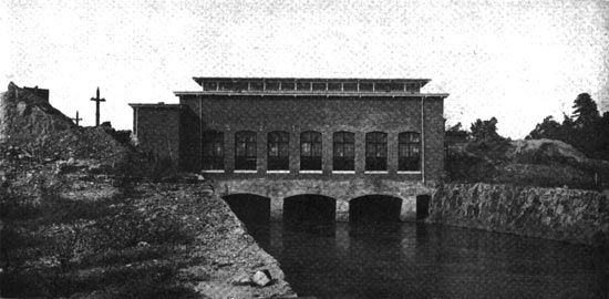
| Fig. 1. -- Power House and Tail-Race. |
The foundations for the entire dam and the anchorages for the abutments are laid on the bed rock. An ample supply of granite was found in the excavations and the near proximity, and this stone was used in the construction of the dam and other parts of the plant. Southern States Portland cement was used throughout in the concrete work, the standard mixture being one part of cement to two and one-half parts of sand and five parts of two-inch mesh broken stone.
The entire dam is faced on the upstream side with a layer of massive granite, approximately two feet in thickness. This face of the dam is vertical, the batter being on the downstream side.
The canal, conveying the water from the head gates to the forebay, is parallel to the general direction of the river and has a length of 816 ft. One wall of the canal consists of a cut in the hillside; the other, or river side wall, being formed, for a part of its length, by an earth fill over a concrete core wall, and is protected, where necessary, with stone filling. The cut has a slope of one to one, and the fill a slope of one and one-half to one.
Immediately below the head gates in the river side wall of the canal, is placed an auxiliary spillway, having an elevation of one foot more than the main spillway, and sufficient area to discharge all of the water which the head gates are capable of admitting. This spillway protects the canal and forebay from overflow in case of a sadden shutdown of the water wheels, from any cause.
The forebay, like the main dam, is built of cyclopean concrete and contains a second pair of trash racks, the penstock gates and the air vents. The penstocks are, in reality, simply extensions of the wheel casings, and are securely anchored into the forebay masonry. The penstocks and wheel casings are made of three-eighths-inch boiler plate, single riveted.
It was found expedient to run the county road immediately over the wheel casings, so the penstocks and wheel casings were encased in a mass of concrete masonry, forming a practically solid structure from the forebay to the power house wall. Each of the penstock gates is fitted with a priming or filling gate to facilitate operation. Manholes in each wheel casing provide access for inspection and adjustment.
Each of the main prime-mover units consists of a set of three, thirty-nine-inch inward flow turbines, fitted with cylindrical gates and having an aggregate capacity of 1,700 hp per unit at full gate when operating under 35 ft. head and running at a speed of 200 r.p.m. Three of these units are installed, each unit being directly connected by a face plate coupling to a 1,000-kw generator. A 15-in. turbine is installed for driving one of the exciter units and an 18-in. turbine for driving a small alternating-current generator.
The speed of each of the main units is controlled by a Holyoke "Improved" governor, operating on oil pressure, and furnished complete with oil tanks and pressure pump, the pump being belt-driven from the shaft of the prime-mover unit. A small compensating Woodward governor is installed for each of the 15-in. and the 18-in. wheels.
| |||
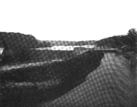
| Fig. 2. -- Canal and Dam. |
Draft tubes of ample cross-section convey the water from the wheels to the tail-race, the ends of the tubes being well submerged and the tail-race excavated for a sufficient depth immediately below the tubes to prevent foaming. The normal elevation of the tail-race water is 36 ft. lower than the crest of the spillway of the main dam. The tail-race is approximately 338 ft. long, and is lined with massive stone masonry set in cement.
The generating machinery is placed in a substantial brick and steel building, 83 ft. long and 35 ft. wide and resting on the concrete arches and bed rock foundations. The building is provided with ample window openings and has a large monitor in the roof, giving good light and ventilation. The floor of the power house is served by a Niles-Bement-Pond traveling crane of 15 tons capacity. The step-up transformers are placed in a separate room at one end of the main building. This room contains also the lightning arresters, oil switches, etc., and is separated from the main building by a fire wall fitted with an automatic fire door placed on a level with the switchboard gallery.
The main electrical generating units consist of three 1,000-kw, three-phase, 2,300-volt, 60-cycle, revolving-field generators, each directly coupled to one set of three water wheels and running at a speed of 200 r.p.m. The generators are of the open frame type of construction and are furnished with cast-iron bases and have the shafts extended for the reception of an exciter driving pulley. The armature windings are of the distributed type, with three slots per pole per phase, and are star-connected.
The generators are guaranteed to have the following characteristics: Efficiency, full load, 95 per cent; three-fourths load, 94 per cent.; one-half load, 92 per cent; voltage regulation from full non-inductive to no load, 8 per cent.
A 100-kw, three-phase, 60-cycle generator, running at a speed of 600 r.p.m., and generating current at 2,300 volts, is directly coupled to the 18-in. water wheel. This unit is used at night for lighting service, after the main power generators are shut down. A 5.5-kw exciter is provided for this generator and is driven from a pulley on the extended shaft of the generator.
The plant is equipped with two main exciters, one of 55 kw capacity directly coupled to the 15-in. water wheel and running at a speed of 625 r.p.m., and one of 58 kw capacity at 925 r.p.m., the latter so arranged that it can be driven by a belt from a pulley on the shaft extension of either one of two of the main generators. The water wheel-driven exciter gives somewhat better voltage regulation and is used in normal operation, the belted machine being held as a reserve. Each of the exciters has sufficient capacity to excite all of the main generators, under the extreme conditions of load and power factor met with in the operation of the plant.
| |||
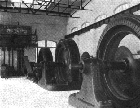
| Fig. 3. -- Interior of Power House. |
The cables connecting the generators with the switchboard are insulated with varnished cambric and are lead-covered. These cables are laid in impregnated fibre conduit, set in the concrete floor of the station. The switchboard is mounted on a gallery at one end of the power house, and immediately in front of the transformer room. The gallery is of sufficient height to enable the operator to have an unobstructed view of all the machinery.
The switchboard consists of four generator, two exciter-generator and two step-up transformer panels. The material of the panels is blue Vermont marble and the instruments are nickel finished. The panels have a uniform height of 62 in. with a sub-base 28 in. high, and are 2 in. in thickness. All of the generator panels are 24 in. wide and the transformer panels are 16 in. wide.
The oil switches for the generator and transformer panels are placed in separate cells mounted on a gallery in the transformer room (this gallery being a duplicate of the one in the main room and placed on the same level with it). Operating rods run through the dividing wall and connect the oil switches with their respective mechanisms on the face of the switchboard.
The panels are equipped with horizontal edgewise instruments and all devices desirable for the flexible operation of the plant. The generator switches are non-automatic, the transformer switches being automatic with time-limit relays.
| |||
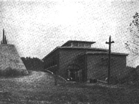
| Fig. 4. -- Exterior of Power House. |
Installed in the transformer room are six water-cooled 500-kw transformers, which raise the potential of the system from 2,300 to 22,500 volts. These transformers are installed in two banks of three each, and are delta-connected on both the low and high-tension sides. The transformers have the following guaranteed characteristics: Full load efficiency, 97.7 per cent; regulation from full non-inductive load to no load, 1 per cent. The water for cooling the transformers is drawn direct from the penstocks. As. this water contains, at times, a considerable quantity of silt, liable to precipitation in the cooling coils, a pressure pump is installed for blowing out the sediment at intervals.
Each bank of transformers is connected to a set of high-tension bus-bars, which are in turn connected through the medium of air break disconnecting switches to the one outgoing line. During normal day load operation both banks are connected to the line and operated in multiple, but at night only one bank is retained in service.
The lightning arresters also are placed in the transformer room and are equipped with choke coils and disconnecting switches. The arresters are of the multiplex type, of multi-gap construction, with graphite resistance in series with the gaps.
The three conductors of the transmission line leave the transformer room through terra-cotta tiles, set in the wall at an angle to prevent the entrance of rain. From the generating station, the first section of the transmission line is carried to a junction point, from which the lines to Belton and Williamston diverge. This first section of the transmission line is 4.1 miles long and consists of three cables of 165,160 cir. mils each. The line from the junction to Belton is 4.4 miles long, with 103,800 cir. mils cables, and the line to Williamston, 5 miles long, with 82,340 cir. mils cables. All of the power conductors are of aluminum, seven-strand cable. Joints were made in the cable, where necessary, with flat aluminum tubes, of such size as to snugly fit the ends of the cable and firmly secured by two complete twists.
The power conductors are placed in the form of an equilateral triangle with a distance of 48 in. between centers. Poles are spaced 120 ft. apart on the levels and the average height of the lower conductors above level ground is 30 ft. The pole line is carefully graded in height, by using long poles in the low places and short ones on the crests of ridges. The poles are of pine, impregnated by vacuum process with creosote. The cross-arms are of pine, have a cross-section of 5 in. by 6 in., and are also impregnated with creosote. The cross-arms are set in 1 ½ in. gains, and are secured to the pole by two 5/8-in. bolts. Each crossarm is braced by two 1 1/2 in. by 1/4 in. braces 30 in. long, secured to the cross arm by 3/8-in. carriage bolts, and to the pole by a 1/2-in. by 5-in. lag screw. All braces and bolts are thoroughly galvanized.
The top insulator pin is bolted to a cap casting, fitting over and securely bolted to the pole top. All of the pins are of the porcelain base type, Locke No. 24 being used for the top and No. 19 for the cross-arm construction. Each pin is secured by means of a 3/4-in. galvanized steel bolt. The insulators are of the single petticoat type, have a diameter of 6 3/4-in. and an overall height of 5 3/4 in., and are made of brown porcelain. The power conductors are fastened to the insulators by means of tie wires of solid No. 1 B. & S. soft aluminum wire.
An improvised form of disconnecting switch is installed at suitable intervals along the transmission line, so that in case of necessity, or for testing purposes, the line may be sectionalized. The switch consists of two strain insulators, joined together at a suitable distance apart by a substantial wood framing, and an aluminum clamp. Each cable end is dead-ended to one of the strain insulators, the loose ends being joined together by the clamp. These switches are bolted, two to the cross-arm and one to the pole top at right angles to the cross-arm. They are, of course, suitable for operation only when the lines are not carrying current.
Strain insulators are used at such points where it was found necessary to change the direction of the line, a special form of iron brace being used for the top insulator, and where the angles were severe, double cross-arms were used for the lower wires. At such points the poles are securely guyed to anchorages, and the line is head guyed at approximately every tenth pole. Right-of-way was cleared and is maintained for a sufficient distance on each side of the line to prevent injury from falling trees or limbs.
The telephone wires are placed on the same poles as the power conductors and 4 ft. below them. No. 10 B. W. G. galvanized steel wire is used for the telephone lines, supported on standard glass insulators and wooden brackets and transposed at every fourth pole. An auxiliary telephone line is also installed, running on separate poles and by a different route and right-of-way. In addition to the instruments in the power station, sub-stations and office, a portable set is provided for each of the linemen.
Lightning phenomena in this section of the country are very severe, and a grounded guard conductor is installed to assist in eliminating disturbances on the transmission line. This guard conductor consists of a 3/16-in. galvanized steel cable, supported by the lower cross-arm to which it is secured at the side of the pole, its position being practically at the center of the base of the triangle of power conductors. The guard conductor is grounded thoroughly at every sixth pole.
One sub-station is located at the town of Belton, the other at Williamston. The sub-station at Belton contains three 667-kw water-cooled transformers, stepping down from 22,500 volts to 600 volts. These transformers supply power to the Belton Mills. The primaries of the transformers are connected in delta, the low-tension secondaries being connected in star with the neutral grounded, so as to obviate the possibility of the high-tension current entering the mill, in the event of a break-down in the insulation of one of the transformers. In a separate room of this sub-station are installed two 25-kw transformers, supplying current at a potential of 2,300 volts, three-phase, for the lighting of the town and the operation of small motors. These transformers are connected "open delta" on both the high and low-tension sides. A 25-light, air-cooled, constant-current transformer supplies current at 6.6 amperes for the operation of the series street arc lighting system.
The Williamston sub-station is practically a duplicate of that at Belton, except that the apparatus is smaller. Three 333-kw transformers supply power at 600 volts to the Williamston Mills, and a single 25-kw transformer is installed for the lighting of the town.
Each of the sub-stations contain an automatic, triple-pole oil switch, each pole mounted in a separate cell and operated together from one shaft and mechanism. These switches are operated by means of trip coils actuated by time limit, overload relays, Multiplex lightning arresters, duplicates of those at the power station, are installed in each of the sub-stations.
Both the Belton and the Williamston Mills are equipped with complete steam plants, having been so operated before the advent of the electric power. These steam plants are now held as reserves and are ready for prompt service in the event of an accident to the electric system. The shafting of the mills is so arranged that the drives can be changed from electrical to mechanical, or vice-versa, in a very short time.
The group electric drive is used in both mills, induction motors of standard speeds and varying in size from 50 to 300 hp being installed. The load is practically constant for 11 hours during the day; and as there is no night work in the mills, only the comparatively small lighting load of the towns is carried during the night.
The water-wheels, together with the gate irons, penstocks, draft tubes, governors and other accessories were furnished by the Holyoke Machine Company, of Worcester, Mass. The entire electrical equipment, including the apparatus for both the substations and the generating station, was furnished and installed by the General Electric Company. This same company furnished and installed also the electrical equipment in both of the mills. The complete hydraulic and electric plant was designed by, and constructed under the supervision of Mr. J. E. Sirrine, of Greenville, S. C.
Mr. John B. Adger is president of the power company, and Mr. William Harrison Trammell is the general superintendent. The company maintains its executive offices at Belton, S. C. The plant was put in operation on November 25, 1905.
