Neversink Light & Power utilizes Floy insulators
|
[Trade Journal] Publication: Electrical World and Engineer New York, NY, United States |
||||||||||||||||||||||||
|
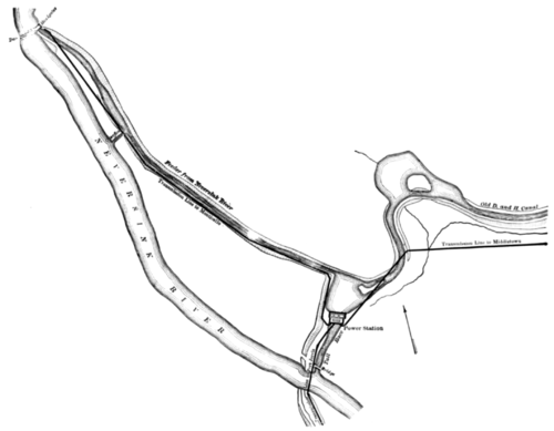
Hydraulic-Electric Development of the Neversink Light and Power Company, Middletown, N. Y. AN interesting hydraulic-electric development has recently been completed in the Neversink Valley, Orange County, N. Y., through the use of the abandoned works and canal of the Delaware & Hudson Company. The old Delaware & Hudson Canal, which during more than half a century served for the transportation of stone coal from the region of Pennsylvania to Kingston, N. Y., on the Hudson River and to tidewater, was abandoned under a special act of the New York State Legislature passed in 1900. The canal has always taken its supply of water for its highest level, known as the Summit, from the Neversink River, of Ulster, Sullivan and Orange Counties, N. Y. The canal company maintained a dam across the river which diverted the water into a feeder about one mile long, the lower end of which supplied the canal at such an elevation as to permit the canal being carried across and above the river by means of a cable suspension aqueduct. The hydraulic development, including the dam, feeder and the part of the canal now owned by the Neversink Company, cost the Delaware & Hudson Company originally considerably in excess of a quarter of a million dollars. The abandonment of these works for canal purposes made them readily available for the hydraulic power development, and by raising the embankments a head of about 4o ft. was afforded at the lower end of the feeder. Reference to the ac- companying map will show the relative location of the dam, river and canal.
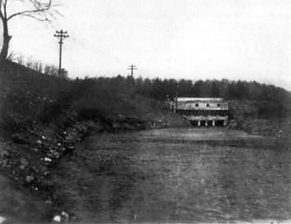
About a year ago the Neversink Light & Power Company entered into a contract for carrying out the complete improvements con templated, including the transmission lines, aggregating 35 miles, to supply energy to Middletown, Port Jervis, Monticello and Liberty, N. Y. The work was carried on so energetically that despite un- foreseen difficulties in execution, labor troubles and delays of manufacturers in deliveries of apparatus, the plant was put in operation the first of the present year. In order to secure the advantages of a storage reservoir, the Neversink Company acquired title to about two miles of the canal A cut-off dam was built across one end of the canal and the other end enlarged so as to make a good-sized basin or forebay, into which the feeder empties and on which is located the power house. This forebay with the two miles of canal and the one mile of feeder and the considerable poundage above the dam makes a reservoir offering storage sufficient to operate the plant at its full capacity for six hours without there being delivered any water from the river. A more practicable way of considering the capacity and usefulness of the storage reservoir would be to say that the plant has a capacity of 1,500 hp for 6 hours even when the flow of the stream reaches its minimum, which is 1,000 hp 24 hours per day. The dam is of concrete steel, 188 ft. long and varying for 10 to 15 ft. in height.
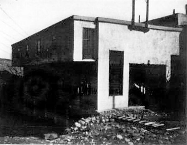
An entirely new entrance has been constructed of concrete at the head of the feeder. A heavy pier or abutment 15 ft. high serves as an anchorage to one end of the dam and a support for the concrete arches over the gateways controlling the admission of the water to the feeder. The gates, three in number, are built of heavy oak planks, having iron tongues and each cover a waterway of 55 square feet. The gates are operated by massive geared crabs, which permit one man to hoist or lower a gate under the extreme conditions of head and pressure to be met. A unique feature of the installation is the use of concrete steel in the design of a combined dam and power house. The structure was built directly across the old canal and although there is a head of 23 ft. on the walls surrounding the wheel chambers the walls themselves are only 3 ft. thick at the bottom, tapering to 14 in. at the top. If steel had not been used with the concrete and the walls properly designed to withstand the overturning moment, they would have been perhaps 10 ft. thick at their base. In front of the penstocks is a large chamber running entirely across the front of the building with concrete walls on either end and an iron inclined rack on its front to prevent ice and debris from entering the wheels. The rack is supported on a massive iron beam construction and has an area of some 1,200 square ft., so that the velocity of the water even when the wheels are operating at full gate will not exceed .3 (3/10) of a foot per second.
The wheel chambers are each provided with three oak gates of sufficient area to allow slow movement of the water to the wheels. The gates are similar to those at the head of the feeder and are operated by crabs on top of the masonry. The power house is of concrete steel throughout, including the roof, floors and girders, walls and foundations, and is built under the Ransome patents. The building is 40 ft. x 60 ft. in plan and is 45 ft. in height. Three wheel chambers are provided, two of which contain pairs of 27-in. horizontal S. Morgan Smith Company, McCormick wheels, and also a single 15-in. wheel direct-connected to an exciter. The third wheel chamber has been built with the expectation that another 550-hp until, the size of those already installed, will be later added when the market for the power is developed. Each pair of large wheels and each exciter wheel is provided with a 17-ft draft tube.
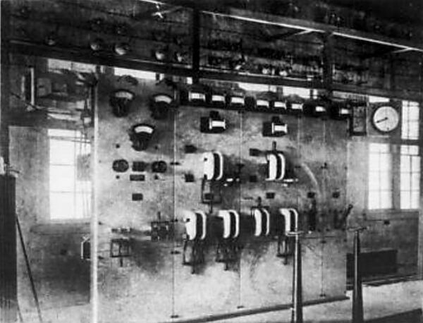
The steel flume heads are built into the concrete-steel wall, separating the wheel chambers from the dynamo room. The shafts of the wheels project through the flume heads and by means of flexible couplings are direct-connected to the alternators and exciters. The generators were furnished by the General Electric Company and are each of 300-kw capacity, three-phase, 60-cycle, 600 volts, revolving field type, running at 300 r.p.m. The exciters are each of 30-kw, 125-volt, direct-connected type of sufficient capacity to excite all three alternators. The switchboard is of, marble, also furnished by the General Electric Company, and supplied with all the latest and most approved instruments, in the way of voltmeters, wattmeters. switches, etc. The switchboard is equipped with two sets of three-phase bus-bars, from which current is supplied to two separate banks consisting each of three transformers. Current from the transformers is fed to two separate sets of three-phase, high-tension bus-bars, running the length of the station. Each conductor of the six three-phase circuits entering the building may be connected by means of a jaw switch to either set of the high-tension bus-bars, providing an arrangement for supplying any transmission line from either generator or operating the railway and motor load in various towns from one set of bus-bars with its generator, and the lighting load from the other set with its generator.
The step-up transformers are of the oil-insulated, self-cooling type. Those in the station are of 100-kw capacity, each provided with special taps to permit of adjustment of the voltage and installation of the Pearson-Cutcheon Lightning Protection device. The transformers step up from 600 to 10,000 volts, which latter pressure 1s the potential of transmission on all circuits. The step-down trans- formers in Middletown and Port Jervis are each of 50-kw capacity, and they are also provided with taps for adjustment of voltage. They were furnished by the Westinghouse Electric & Manufacturing Company. Two types of governors are used and an interesting test as to their comparative merits in controlling the speed of the water wheels is being made. One governor of each make has been installed and as each controls the speed of a separate generating unit, in all respects identical with the other, every facility is offered for deter- mining which governor is the most satisfactory both as to speed regulation and general working.
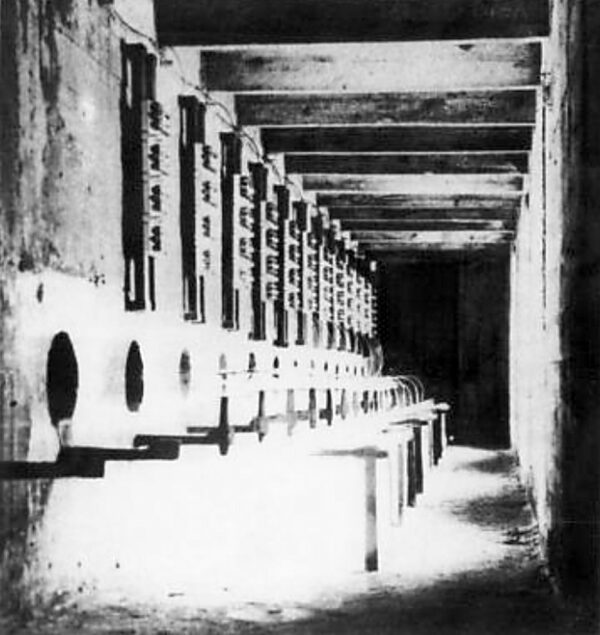
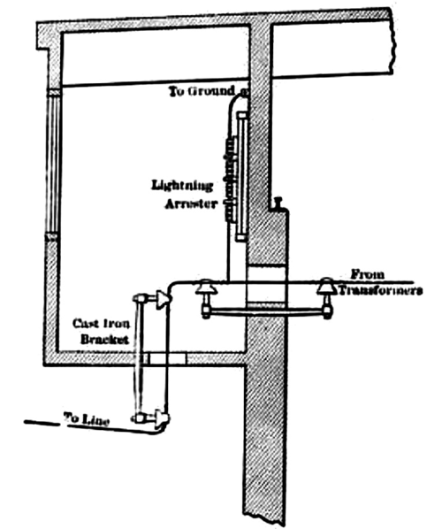
The station is provided with an overhead traveling crane furnished by the Niles Tool Works, electric heaters, telephone switchboard, air compressor and the other small but necessary adjuncts for a complete station. The three transmission lines are built in the most thorough and substantial manner. On all lines the poles are 30 ft. or more in length and 7 in. in diameter at the top, set 5 ft. in the ground and spread 120 ft. apart. They are each equipped with two cross arms for the twin three-conductor transmission circuits, and one cross arm for the metallic return telephone line. The poles are double-cross-armed and guyed at road crossings or slight angles with special three-pole construction at right angle turns. Special high-tension locust pins with Floy triple petticoat glass insulators are used for the high-tension lines. The cross arms are braced and bolted to both the poles and braces. In order to determine whether copper or aluminum conductors are the more satisfactory, there has been installed on each trans- mission line one circuit consisting of three hard-drawn No. 6 copper conductors and another circuit consisting of three No. 4 seven-strand aluminum conductors. A novel and what seems unusually satisfactory method of introducing the bare transmission line conductors within the building has been adopted. A gallery overhangs the tail race making a separate room used as a lightning arrester house which extends across the entire south side of the main building. Each bare wire of the 10,000-volt transmission line enters the building first perpendicularly through the floor of the lightning arrester gallery and then horizontally through the wall dividing the lightning arrester room from the generator room. Iron brackets are set both in the floor and dividing wall, so that each conductor is rigidly supported, in the center of a circular hole in both the floor and wall. As the conductor slopes downward from the last pole on the transmission line to the insulator below the lightning arrester gallery and at that point turns abruptly upward, rain following the conductors runs to the insulator and so drops off without entering the building. The arrangement permits the naked conductor to pass through the walls of the building, but also prevents any rain or snow blowing in. Throughout a large part of their length the transmission lines are built across private property in order to secure the shortest route and a right of way which avoids special franchise tax and future controversies. To convey the right to erect, maintain, patrol and operate the transmission lines across such lands there were prepared and used a uniform deed, with spaces left blank for necessary in- sertion, so that future litigation is forever avoided. The president of the Neversink Light & Power Company is Dr. Henry C. McBrair, of Middletown, N. Y., who first recognized the value of the power purposes of the abandoned canal and with indefatigable energy secured control of the properties and arranged for the completion of the development. The Henry Floy Company, of New York, was the contractor for the improvement, including the earthwork, dam, power house, transmission lines and installation of machinery. Mr. W. A. Gordon, as resident engineer in charge of the work, should be mentioned for the very creditable way in which the details have been carried out and the engineering difficulties over-come. Mr. C. E. Breckenridge, of the same company, has had charge of the installation of the transmission lines, which are more than usually substantial and well built.
|