Hudson River Project - Part I
|
[Trade Journal] Publication: Electrical World and Engineer New York, NY, United States |
||||||||||||||||||||||||
|
Transmission of Hudson River Power.I. ENERGY from the Hudson River is to displace more than 40,000 hp of steam apparatus in the triangular territory between Albany, Schenectady and Glens Falls, N. Y. The extent of this territory in a direct line between Albany and Glens Falls is about 45 miles, and the cities of Albany and Schenectady are 15 miles apart. Within the area named are Troy, Albany, Schenectady, Cohoes, Lansingburg, Ballston Spa, Saratoga, Fort Edward, Sandy Hill and Glens Falls, with an aggregate population of 300,000. This water power is to be transmitted from two generating stations owned by the Hudson River Water Power Company, one located at Spier Falls and the other at Mechanicsville. From these generating plants a network a transmission lines extends to all the cities and towns above named, and also to a number of electric railway sub-stations scattered over the territory. A part of the energy developed at these two water power plants goes to substations owned by the company at Glens Falls, Saratoga and Ballston Spa, where the local systems of electrical supply are also in the hands of the company. Besides the energy required for these systems the Hudson River Water Power Company has contracts with the following companies for the delivery of the amounts of power named, as soon as the water power plants can deliver it, or by fixed dates: General Electric Company, 10,000 hp; United Traction Company, of Albany, 6,000 hp; Hudson Valley Railway Company, 2,000 hp; Municipal Gas Company, Albany, 8,000 hp; Troy Lighting Company, 8,000 hp; Glens Falls Portland Cement Company, 1,000 hp.
These contracts, it will be noted, aggregate 35,000 hp, without taking any account of the regular lighting and motor loads in Glens Falls, Saratoga and Ballston Spa, where the company is now operating the electrical supply systems. Besides all the above, applications are on file for more than 6,000 hp for use in Saratoga, Glens Falls, Ballston Spa, Sandy Hill and Fort Edward. In order to carry the total of the loads just named, the new power plant at Spier Falls and the remodeled plant at Mechanicsville are being pushed to completion as fast as possible. The ELECTRICAL WORLD AND ENGINEER of June 27, 1903, gave some account of the water power development at Spier Falls, and of the great dam and power house going up there. As then noted, the capacity of the ten main generators at Spier Falls will be 24,000 kw, or 32,000 hp at normal rating. In the Mechanicsville plant the normal generator capacity for the seven units is 7,000 hp, giving thus a normal rating of 39,000 hp for the two water-driven stations. Both plants when completed will have water wheels with materially larger capacities than the generators to which they are connected, so that the generators can be overloaded to some extent when desirable.
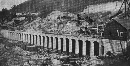
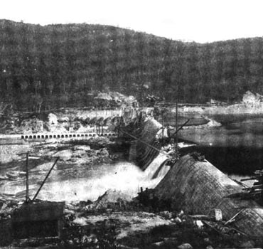
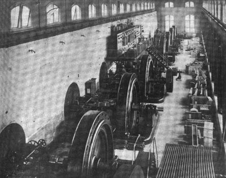
Since the former matter was written on the plant at Spier Falls work on the dam and the foundations of the power house has gone rapidly forward, so that the two 2,000-kw and one of the 2,500-kw generators are in operation, though the full head of 80 ft. of water is not yet available for their wheels. At the present time a portion of the overflow section of the dam has been left a few feet below its final level, pending the completion of the river section, and the head of water at the wheels is about 60 instead of 80 ft., the final figure. In spite of this reduced head the generators are carrying their loads in a satisfactory way, because of the large capacities of their wheels. The foundation of the power house as well as its floor is entirely concrete masonry above the natural rock of the river bed and bank. This foundation and the floor of the power house have been completed, so that it is possible to erect and operate the generators, though the remainder of the power house is lacking, and so urgent is the demand for power that this has already been done as above noted. To protect the generators, transformers and other apparatus a temporary wooden building has been erected pending the completion of the brick power house. This power house when finished will be 70 ft. 10 in. x 392 ft. inside, save that a space 28 ft. x 34 ft. is omitted at one corner. A space extending across the entire width of the building and 40 ft. in the direction of its length is devoted to the transformers and the high and low-tension switchboards. The remainder of the power house is divided into two parts in the direction of its length by a watertight brick partition that gives the wheel room a width of 34 and the generator room a width of 35 ft. Along the outside wall of the wheel room ten steel penstocks each 12 ft. in diameter enter from the canal. Each of eight of these penstocks supplies water to one pair of horizontal turbine wheels that discharge through a single draft tube, and are direct-connected to a 2,500-kw generator. Each of the other two penstocks supplies one pair of wheels that is direct-connected to a 2,000-kw generator and also a wheel connected to a 200-kw exciter. Each of the pairs of wheels is regulated by a Lombard governor. The 2,500-kw generators operate at 240 r.p.m., 40 cycles, three-phase and 2,000 volts. The 2,000-kw generators have a speed of 300 r.p.m. and also develop 40-cycle, three-phase, 2,000-volt current. That section of the power station containing the transformers and switchboards adjoins the dam and has a basement underneath the main floor. This basement with the dam for one of its side walls and its floor, roof and other sides formed of concrete masonry, contains a central air chamber where a pressure of % ounce per sq. in. is maintained by blowers in order to force air through the transformers that sit on the main floor above it. On that side of this air chamber which is nearest to the main generator room is the low-tension switchboard, where the 2,000-volt current from the generators is received. On the opposite side of the air chamber and basement is the lower portion of the 30,000-volt switchboard, the upper part of which runs above the main floor. With this latter switchboard are included the motor-operated oil switches, through which the 30,000-volt windings of the transformers are connected to the transmission lines. Each phase of these switches is contained in a separate brick compartment. The 30,000-volt connections are mounted on the stone and concrete masonry by means of Locke porcelain insulators. Each insulator for this purpose is secured to an iron pin and has a cast-iron cap. The joint between the pin and insulator, and also the joint between the insulator and the iron cap is made with a thin mortar of neat Portland cement. Insulators with pins and caps of this sort are used to support not only the connections but also the knife switches for the 30,000-volt lines. One of these knife switches is located in each wire on each side of every oil switch, so that the oil switch may be entirely disconnected from the line wires and transformers when any work on the switch is to be done.
In the complete equipment of the Spier Falls station are included thirty transformers of the air-blast type, designed to operate at 2,000 volts primary and either 15,000 or 30,000 volts secondary. Each of 24 of these transformers is rated at 833 kw, and each of the other 6 transformers is rated at 670 kw. The 833-kw transformers are connected in groups of three with the 2,500-kw generators, and each group of three 670-kw transformers is connected to a 2,000-kw generator. Six three-phase transmission circuits are to leave the Spier Falls station, and each of the eighteen wires that make up these circuits will be connected to a ground plate through a knife switch and a series of twelve lightning arresters mounted in a stone and brick cell. Each of these lightning arresters is of General Electric make and includes two carbon resistance rods and five brass cylinders with four air-gaps between them, all mounted on a porcelain base. The length of the air-gaps between cylinders varies somewhat and appears to range between 1/32 and 1/16 in.
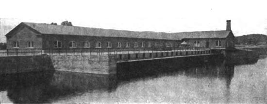
Each of the two exciters at the Spier Falls station has a capacity of 200 kw and is driven by water from one of the penstocks that supply the wheels of the 2,000-kw generators. The operating switchboard is located in front of the row of main generators and about midway of the length of the station. On this operating board are the switches that start the motors on oil switches of the high-tension lines. Besides the equipment of indicating meters there are also recording wattmeters for the entire output. About 25 miles in a direct line from the Spier Falls station, though at a somewhat greater distance by the course of the river, is the second water power plant of the Hudson River Water Power Company, namely, that at Mechanicsville. This plant, as at first built, was completed in 1898, and described by the ELECTRICAL WORLD AND ENGINEER in September of that year. The Hudson River at the point where the dam and power house were built has a total width of about 1,200 ft. At a distance of about 800 ft. from the eastern bank of the river a rocky island divides the channel into two parts, and across the greater of these parts the main or overfall section of the dam was built. The length of the overfall section of the dam between abutments is 707 ft., but the spillway has recently been increased 143 ft. by the removal of the soil from the ledge at the eastern end of the dam, and the construction of a crest there that is one foot higher than the crest of the original overfall section. This section stands 15 ft. above the bed rock of the river, is 16 ft. thick through its base, 8 ft. just below the crest, and 30 ft. thick through the base and apron. From the western bank of the river the power station extends a distance of 215 ft. toward the island, and the remaining width of the channel is closed by a dam 26 ft. high, 10 ft. wide on top and 18 ft. wide at the base. In the section of dam last mentioned are four arched waste gates each 4 ft. wide and 6 ft. 9 in. high. In the western abutment of the main dam there are 12 waste gates each 4 ft. wide and 6 ft. high. From the foregoing it may be seen that the power house forms one section of the dam across the western channel of the river. In total length the power house measures 257 ft. 6 in., and its width up and down stream in the river section is 66 ft. 6 in. Of this total width the wheel chambers on the upstream side take up 32 ft. 6 in., and the generator room on the downstream side has 34 ft. Up to the level of the floor of the generator room the power house, like the dam, is constructed of concrete masonry, but imbedded in the concrete arches and piers beneath the power house are steel I beams and columns. Above the main floor on the downstream side, and above the wheel chambers on the upstream side, the power house walls are of brick with steel columns at intervals that carry the steel roof trusses and the traveling crane on 20-tons capacity. The upstream half of the power house is divided into nine wheel chambers which have arched concrete roofs as well as concrete floors and sides. The head wall that separates each wheel chamber from the generator room is 6 ft. thick and is fitted with a large bulkhead of cast iron that carries a watertight bearing for the wheel shaft. Each wheel chamber connects with the west channel of the river through an arched opening at its upstream end, and this opening is protected by an iron rack to intercept floating objects. Seven of the wheel chambers are designed for wheels that operate the main generators, and each of these chambers is 32.5 ft long, about 18 ft, high, and 23 ft. wide approximately. The head water level in each wheel chamber is 49, and the elevation of the tail water underneath is 31, under normal conditions, so that the effective head on the wheels is about 18 ft. at best. Each set of main wheels is set with its shaft 7 ft. below the normal head water, and 11 ft. above the normal tail water level, and the draft tubes extend some distance below the tail water. As at first constructed by another company, the highest points of the arched openings at the upstream ends of the main wheel chambers were about 2 ft. below the level of the river at that point, but since the plant has come into the hands of the Hudson River Water Power Company a large amount of concrete has been cut from the tops of these arched openings, so that the head water can the more readily flow to the wheels.
In each main wheel chamber four 42-in. diameter turbine wheels were originally mounted on the horizontal shaft, and each pair of these turbines was provided with its own draft tube. Each main wheel shaft, after passing through the cast-iron bulkhead, is coupled to the shaft of a 750-kw or 1,000-hp generator. The four 42-in. wheels were rated to deliver 1,000 hp, but these wheels proved to be too small to drive the 750-kw generator at full load and overload under the variations of head due to changes in the flow of the river. To remedy this defect the 42-in. turbines have recently been replaced by others of 51 in. diameter each. These 51-in. wheels are mounted four on each shaft, like the former ones. The horizontal shafts carrying the turbine wheels just named have a speed of 114 r.p.m. and drive the connected generators at that rate. S. Morgan Smith Company is the builder of the new 51-in. turbines. Each of the two exciters is driven by three 18-in. Victor wheels mounted on the same shaft and operating at 250 r.p.m. All water wheel governors, of which there is one for each set of wheels, are the product of the Lombard Governor Company. Each of the seven shafts driven by the larger water wheels is direct-connected to a 750-kw, 12,000-volt, three-phase, 40-cycle generator of General Electric make, and these generators are of the internal revolving magnet type. Current for the magnets of these generators is supplied by two 100-kw, 125-volt exciters, each directdriven by three of the 18-in. wheels. To provide for the contingency of low water, two Heine water tube boilers rated at 505 hp each, and one Hamilton Corliss tandem-compound engine with cylinders 24 x 48 x 48 in., and rated at 1,000 hp, has been installed. This engine is connected by a rope drive to a short shaft that can be readily coupled to the shaft of the 750-kw generator nearest the river bank when desired.
A switchboard gallery is located on the upstream side of the generator room, and oil switches for all of the 12,000-volt generators and transmission lines are operated from this gallery. A part of these oil switches are operated by hand and a part by motors, but both these types of switches are located in separate fire-proof compartments, the manual switches being beneath the gallery, and the motor operated at one end of the station. These oil switches were all made by the General Electric Company. Air-break switches were at first installed in this station, but they did not prove satisfactory on the 12,000-volt generators and circuits. In addition to the existing stations at Spier Falls and Mechanicville the Hudson River Water Power Company owns a large water power at Ashley Falls, about ten miles northwest of Spier Falls, on the Sacandaga River, and another large power at Gay's Falls, about three miles downstream from Spier Falls on the Hudson River. It is the intention of the company to develop the powers at Ashley and Gay's Falls in the near future. From the plants at Spier Falls and Mcchanicville current is to he transmitted to sub-stations of the Hudson River Water Power Company at Glens Falls, Fort Edward, Saratoga, Ballston Spa and Watervliet. The Glens Falls, Saratoga and Watervliet sub-stations ;ire already in operation, and construction of the Fort Edward and Ballston Spa sub-stations is underway. Besides its own sub-stations just named, the water power company is delivering energy to a number of sub-stations along the line of the Hudson Valley Railway, which extends from Troy to Mechanicville, Saratoga and Glens Falls, to sub-stations of the Schenectady Street Railway at Ballston Spa, Schenectady, Colone and Latham's Corner, to a sub-station in the General Electric Works at Schenectady, to sub-stations of the United Traction Company, of Troy and Albany, located at North Albany and Watervliet, respectively, to a sub-station of the Albany Electric Illuminating Company, to the Lighting Company, of Troy, and to a sub-station of the local lighting company in Lansingburg. To transmit energy from the plants at Spier Falls and Mechanicville to the various sub-stations named the following three-phase circuits will be employed, all circuits being made up of copper wires hard-drawn and solid. Between Spier Falls and the sub-stations at Glens Falls and Fort Edward, a distance of about 10 miles, there is a single circuit of 3/0 wire. From Spier Falls to Saratoga switch house three circuits of 3/0, and two circuits of 1/0 wire will be employed. One circuit of the 1/0 wire goes from Saratoga switch house to Saratoga sub-station, a distance of about two miles, and terminates there. Two of the 3/0 circuits pass from the Saratoga switch house to the sub-station of the Hudson River Water Power Company at Watervliet, which is about 35 miles from the power plant at Spier Falls. The remaining, one 1/0 and one 3/0 circuits, go from Saratoga switch house to Alplaus switch house, which is about five miles from the sub-station in the General Electric works at Schenectady. From Alplaus switch house two 3/0 circuits pass to the General Electric sub-station, distant about 32 miles in a direct line from Spier Falls. Both the circuits between Saratoga switch house and Alplaus switch house pass through the sub-station at Ballston Spa, which is 17 miles south of the generating plant. Alplaus switch house is connected with the water power company's sub-station at Watervliet by one circuit of 3/0 wire. Between this Watervliet sub-station and that of the Albany Electric Illuminating Company there are two circuits of 3/0 wire. This Albany sub-station is about 41 miles in a direct line from Spier Falls, but the distance by line is somewhat greater. The sub-station of the local lighting company in Troy is connected with the Watervliet sub-station by two 3/0 circuits, and the last-named sub-station feeds that of the United Traction Company at North Albany over one circuit of 1/0 and one of 3/0 wire. A circuit of 1/0 wire connects the Watervliet sub-station of the power company with the Latham's Corner sub-station of the Schenectady Street Railway, and this circuit has been continued by the railway company to the sub-station in the General Electric Works. Three circuits each of 3/0 wires leave the water power plant at Mechanicville. Two of these circuits pass to the Watervliet sub-station and one goes to the switch house at Alplaus. Of the above-named circuits, three of 3/0 wire between Spier Falls and Saratoga switch house, and two of 3/0 wire between Saratoga switch house and Watervliet sub-station have not been erected, but it is the intention to complete them at an early date. When the power plants at Gay's Falls and Ashley Falls are in operation their transmission lines will join those already named at Spier Falls.
|