Puyallup River Water Power Development Near Tacoma, Washington II
|
[Trade Journal] Publication: Electrical World and Engineer New York, NY, United States |
||||||||||||||||||||||||||||||||||||||||||||||||||||||
|
The Puyallup River Water Power Development Near Tacoma, Washington.II. (Concluded.) SWITCH HOUSE ARRANGEMENT.
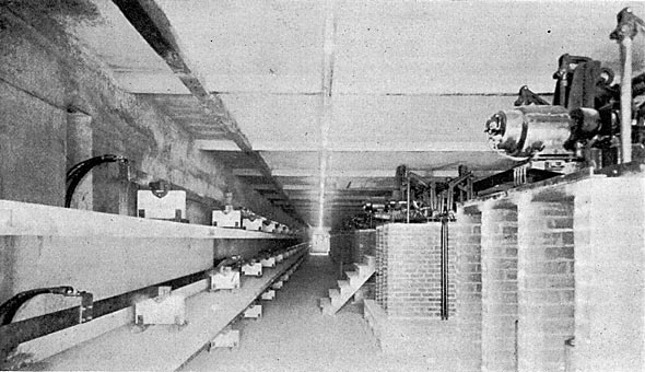
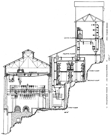
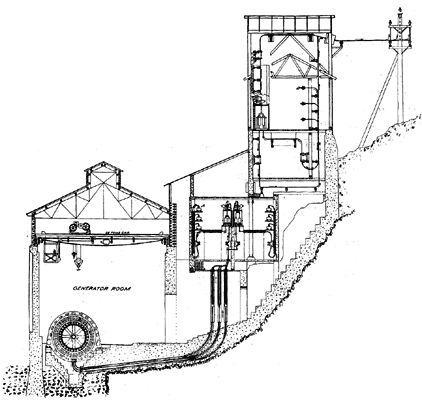
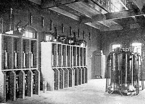
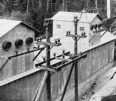
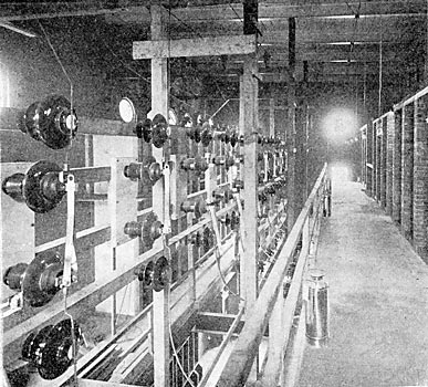
F IGS. 53 and 54 show sections through the generator room and switch house. The transformer rooms are at the same level as the generator room; but isolated from the latter by rolling steel doors. On floor No. 2 are the low-tension disconnecting switches, the generator and transformer cables going to the sets of disconnecting switches on either side of the middle partition; the disconnecting switches are installed between the oil switches and the bus, being on the outer walls and immediately below the bus bar compartments, which are above on floor No. 3. In the center of floor No. 3 are the low-tension oil switches, the two oil switches corresponding to a generator or transformer bank being arranged back to back and facing their corresponding set of bus bars. The bus bars are of the laminated type, consisting of flat copper bars with expansion joints and supported on marble slabs set on edge, which in turn rest on concrete slabs forming barriers between adjacent bus bars. The compartments formed by the concrete slabs are to be covered by insulating fireproof doors.
The oil switches are installed in brick cells with soapstone bottom and top slabs and doors. Each pole of a switch is separated from the other poles by brick barriers. The same general scheme is used for both the low and high-tension disconnecting switches and oil switches, except that only one set of high-tension bus bars is at present installed, provision being made for the later installation of the second set. The high-tension disconnecting switches and current transformers are on floor No. 5, while the high-tension oil switches are on floor No. 6. Above floor No. 6 are the two outgoing high-tension line towers, in the north end of which are the high-tension lightning arresters, each pole being separated from its adjacent pole by brick barriers extending the full length of the arrester. The lines emerge from the wire tower centrally through an extra heavy 30-inch sewer tile covered by a glass plate (Fig. 20).
TRANSMISSION LINE.
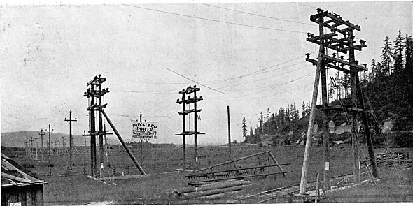
From the power house two parallel transmission lines run a distance of 22 miles to Bluffs, a station on the line of the Puget Sound Electric Railway, g miles from Tacoma and 25 miles from Seattle. From Bluffs one line runs for a great part parallel to the transmission line of the Puget Sound Electric Railway to Seattle and one to Tacoma, also parallel to the transmission line of the Puget Sound Electric Railway.
The transmission line of the Puget Sound Electric Railway is at present operating at 27,000 volts, but the line is designed for operation at double this voltage, so that when it is changed over to a 55,000-volt basis there will be two complete and independent pole lines from the power house to Seattle and Tacoma. At Bluffs there are erected junction pole switches by which the two transmission lines may be cut through independently, one to Seattle and one to Tacoma, or both lines put in multiple, or any section isolated without interfering with the operation of the other sections.
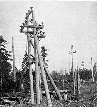
From the power house to Bluffs a private right of way has been secured, the two pole lines being from 50 to 80 feet apart. When passing through wooded sections all dangerous timber has been cleared well back on the land adjacent to the right of way on both sides, so as to completely protect the transmission line. The minimum length of poles used was 45 feet, with a minimum top diameter of 10 1/2 inches. The standard spacing is 125 feet on straight lines and 90 to too feet on curves. The main crossarm is 5 inches x 7 inches x 7 feet 4 inches Washington fir, boiled in raw linseed oil, giving it a much longer life than an untreated arm. This arm is bolted to the pole by two galvanized iron bolts and braced by a combination wood and galvanized iron brace. At the top of the pole is a 5-inch x 7-inch x 18-inch arm supported by an angle iron frame bolted to the pole by two galvanized iron bolts. The main arm supports two insulators, and the top arm one insulator, giving an equilateral triangular spacing of 72 inches between wires. The pins on one line from the power house to Bluffs, and from Bluffs to Seattle and Tacoma, are galvanized malleable iron, cast hollow and circular in cross section and having a shank diameter of 2 1/2 inches. The pins on the other line are of the same general exterior form and dimensions, but turned from eucalyptus wood and treated with linseed oil. The iron pins and eucalyptus pins are entirely interchangeable in all parts of the construction. The insulators are of dark brown glazed porcelain, a portion being furnished by the Locke Insulator Manufacturing Company and a portion by R. Thomas & Sons. The insulators are a special design adopted after tests on a number of samples of varying design. The insulator consists of a broad, umbrella-shaped top 14 inches in diameter, and three inner shells cemented together and to the iron pins by neat Portland cement. They weigh about 22 pounds and stand a potential of 90,000 to 100,000 volts before arcing over under an artificial rain test. The separate parts of the insulators were given a dry potential test at the factory before shipment, and after assembly in Tacoma and before shipping out on the line they were again tested to a potential corresponding to the dry arcing-over voltage. So far the behavior of these insulators under the weather conditions that have existed since the plant was put into operation and under a line voltage of 55,500 volts, has been entirely satisfactory. The line wire on both lines from the power house to Bluffs and from Bluffs to Seattle is 19-strand, 4/0 semi-hard drawn rubber cable, and from Bluffs to Tacoma is solid 1/0 semi-hard drawn copper wire. The wires are transposed, making a third of a turn about every four miles. The telephone line is supported on cross-arms seven feet below the main arm and consists of two No. To hard drawn copper wires, transposed every tenth pole, the glass insulators being double petticoat deep groove on locust pins. The operation of the telephone line with the above construction has been entirely satisfactory. The company also has an independent telephone line leased from the Sunset Telephone Company and constructed over another route.
SUMNER AND PUYALLUP.
Eighteen miles from the power house and along the transmission line from the power house to Bluffs is the town of Sumner. In Sumner has been built a sub-station to accommodate two 100-kw, 50,000 to 2,300-volt transformers for local power and lighting. At present only one transformer has been installed, furnishing current for lighting Sumner. A 2,300-volt line will be built from Sumner to Puyallup, a distance of three miles, for supplying the city of Puyallup with current for lighting and power, taking the place of the steam plant at present in operation.
MASSACHUSETTS STREET SUB-STATION.
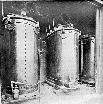
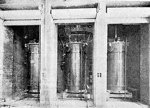
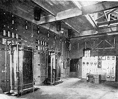
The receiving station in Seattle is built on Massachusetts Street, near the southerly city limits. Here the high-tension current is stepped down to 2,300 volts for local distribution to the stations of the Seattle Electric Company. Control is provided for the two incoming high-tension lines by means of high-tension, motor-operated oil switches, and for two 4,000-kw banks of transformers, and for three outgoing 2,300-volt feeders. The control of the transformers consists of a motor. operated, 60,000-volt, 400-amp. oil switch on the high-tension side of each bank of transformers and a motor-operated, 2,500-volt, 4-pole oil switch on the low-tension side of each bank. The control of the 2,300-volt outgoing feeders is by motor-operated, 4-pole oil switches similar to the transformer low-tension switches, differing only in capacity, the former being 800-amp. and the latter 1,200-amp. capacity. All of the oil switches have time limit relays for automatically opening the switches in case of overload or short circuits. There are installed four 2,000-kw transformers in two banks of two each, transforming from 50,000 volts three-phase to 2,300 volts quarter-phase. The arrangement of the windings is such that 50,000, 40,000 and 25,000 volts can be used on the high-tension side, and low-tension voltages of 13,800, 6,900 and 2,300 volts may be obtained. The two transformers constituting a bank are T-connected, but using the full winding in the teazer transformer rather than 87 per cent. as in the usual Scott three-phase-two-phase connection. This produces only 1,900 volts on the low-tension side of the teazer transformer, with 2,300 volts on the main transformer, and in order to boost this to normal a 200-kw transformer called a compensator having the full ampere capacity in the boosting coil of the 2,000-kw transformer and a ratio of transformation of 1,990/310, is installed. This makes it possible to omit all 87 per cent. taps on the high-tension winding, of which there would be a number, for the three primary voltages above stated, and simplifies the transformer construction. All the transformers, including the compensators, are water cooled, the water for cooling being primarily derived from the city service, but re-cooled by a cooling tower to effect economy by the re-use of water.
There is in addition to the above apparatus two Soo-kw transformers in this station with a ratio of transformation of 25,000 to 2,200 volts, installed for connection to the transmission line of the Puget Sound Electric Railway. For measuring the input of power into the 2,300-volt busses, a graphic recording voltmeter, ammeter and wattmeter are provided, in addition to the integrating wattmeter. Lightning arresters identical with those at the power house are provided for each of the incoming lines. Marble barriers between adjacent poles of the arresters are installed to prevent the traveling of an arc from one leg to another. Four pole static dischargers are installed on the low-tension side of each transformer bank, their purpose being the same as those at the power house. For controlling the voltage of the 2,300-volt outgoing feeders there is installed in each feeder a motor-operated induction regulator each of a capacity of 340 kw. These regulators boost or lower equally each leg of each phase.
SEATTLE ELECTRIC COMPANY'S DISTRIBUTION.
The power is transmitted at 2,200 volts, two-phase, from Massachusetts Street sub-station to Post Street station, and from here also at 2,200 volts, two-phase, to James Street station and Fremont sub-station. Post Street station contains nine 500-kw rotary converters, each with two 300-kw transformers, five giving 500-volt current for railway and four 250-volt current for lighting, also six 50-kw tub transformers for street lighting. This station is a steam relay station and contains two 2,500-kw overload capacity, 60-cycle, 2,200-volt, two-phase alternators, each driven by a vertical compound McIntosh & Seymour engine; also a 1,000-kw lighting and a 500-kw railway battery. The station contains the general switchboard for controlling the whole distribution in Seattle. James Street station contains two 300-kw induction motor generator sets giving 500-volt railway current. It is also a steam relay station with three 150-kw railway generators driven by a double Corliss engine. When operated on a water power basis the railway generators are used as motors to operate the James Street cable road. Fremont sub-station contains two 300-kw motor generator sets, one induction and one synchronous, the motor end of each being 2,200 volts, two-phase, and the generator end 500 volts, direct current. There is also installed a 300-kw railway battery. The Seattle Electric Company has in addition to the above two steam relay stations not used as sub-stations. These are equipped with direct-current machinery for railway and light and have a combined capacity of 1,500 kw.
TACOMA SUB-STATION.
The receiving station in Tacoma is a new brick building, built adjacent, and as an addition, to the steam station of the Tacoma Railway & Power Company. Control for two incoming high-tension lines is provided as described for Massachusetts Street sub-station. One 4,000-kw 50,000 to 2,300 volts transformer bank is installed with automatic oil switch control on high and low-tension sides. There are also installed two 500-kw step-up transformers, transforming from 2,300 volts two-phase to 13,800 volts three-phase for supplying power to Fern Hill sub-station, the Northern Pacific Railway Company's shops and other local consumption not within the range of economical distribution at 2,300 volts. Automatic control of this bank is provided on the low-tension side only by means of a type "H," 4-pole, motor-operated oil switch. Spare transformers for each of these banks are provided. For receiving power from the 25,000-volt transmission line of the Puget Sound Electric Railway, four 200-kw, oil-cooled transformers wound for 25,000 to 50,000 volts, stepping down from 25,000 to 2,30o volts, are installed. The high-tension oil switches are installed on a steel concrete gallery 20 feet above the transformer room floor, the two line oil switches on a gallery at right angles to the length of the building and the transformer switch on a gallery parallel to the length and along the north wall of the building. Directly under the transformer oil switch are the transformers themselves. On the opposite side of the room and parallel to its length and four feet above the floor -are the transformer 2,3120-volt oil switches. One 400-kw induction regulator, similar to those installed in Massachusetts Street substation, controls the potential of the supply bus, being installed between the transformer bus and the supply bus. Apparatus for cooling the transformer circulating water is being installed somewhat similar to that at Massachusetts Street sub-station. The 2,300-volt power is used for lighting and power service in the city of Tacoma partly, and partly converted into 600-volt direct current for railway and commercial motor service. This conversion is effected by two 500-kw induction motor-generator sets, by one 850-kw synchronous motor set, and by 800 kw in belted machines driven by a 1,000-kw synchronous motor. Either this synchronous motor or the 1,000-kw motor driving the 850-kw d. c. generator can be driven by the steam engines which drive on to a line shaft in which these motors are set, being connected at either end by jaw clutches, thus furnishing a supplementary source of supply and reserve for any of the alternating-current distribution, and for the induction motor generator sets supplying current from the railway. A 100-hp induction motor furnishes power for driving a cable road accommodating the hill district of the city. The Tacoma Railway & Power Company operates about 84 miles of track in the city of Tacoma and between Tacoma and the neigh, boring towns of Puyallup, Spanaway and Steilacoom, and also furnishes power for the operation of the trains of the Puget Sound Electric Railway within the Tacoma city limits. At the Fern Hill junction of the Puyallup and Spanaway lines is a steam station of 500-kw capacity. There is being installed in this station a 500-kw synchronous motor generator set, supplied from the sub-station above described by a 13,800-volt transmission line. This same transmission line supplies current for the operation of motors and lights at the shops of the Northern Pacific Railway at South Tacoma and for the operation of induction motors driving air compressors working a Pohle air lift system pumping water for the Tacoma city water supply, near South Tacoma, and for operating a large number of other stationary motors used by various manufacturing concerns.
SYSTEM OF PUGET SOUND ELECTRIC RAILWAY.
The Puget Sound Electric Railway operates an interurban third-rail system between Seattle and Tacoma, traversing the White River Valley, a distance of 36 miles, and also a branch line reaching the town of Renton. Six hundred volt direct current is supplied to the third rail through three sub-stations located at Georgetown, Kent and Milton. Each sub-station contains a bank of transformers stepping down from 25,000 volts three-phase to 2,300 volts two-phase; also a 300-kw induction motor generator set and a storage battery having a rating of 384 kw on the hour basis. Oil switch control is provided on both the high and low-tension sides. From Kent sub-station is operated the city lighting systems of Kent and Auburn, a transformer, separate from those feeding the motor generator set, being provided for supplying this 2,300 volt service. These sub-stations are supplied from the 25,000-volt transmission line previously mentioned, this line having the 25,000-volt transformer relay at both the Seattle and Tacoma ends. When this line is operated at 50,000 volts, transformers for this voltage will be installed in all the sub-stations.
AUXILIARY AND RELAY APPARATUS.
The electrical development has been designed primarily to insure uniform and uninterrupted service. Continuity of service has been insured by the greatest solidity of construction in every part ; by duplicate busses and switches at the power house, duplicate transmission lines and spare transformers at each end of transmission line, so that all repairs can be made without discontinuing service and by having in all the electrical machinery an overload capacity of from 25 per cent. to 50 per cent. In addition to this there are in reserve in Seattle and Tacoma six steam plants of 10,000 kw aggregate capacity and six storage batteries of 2,700 kw aggregate capacity, all electrically interconnected with each other and with the water power plant, and ready for supplementary and relay service.
|