Kern River, CA Power Plant No. 1 - Part III
|
[Trade Journal] Publication: Electrical World New York, NY, United States |
||||||||||||||||||||||||||||||||||||||||||
|
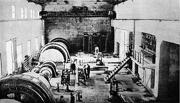
Kern River No. 1 Power Plant of the Edison Electric Company, Los AngelesIII. AI the time work on the Kern River No. 1 plant was commenced five years ago, no plant of its size had been constructed for impulse wheel work. Units exceeding 2000-kw in output were extremely rare and for a long time it was supposed that 2500-kw units would be selected for this station. When, however, specifications were issued, many larger units were in successful operation and prices were requested on machines of 4000 and 5000-kw normal output. No difficulty was anticipated, nor was any experienced in securing generators of this size, but the water-wheel equipment presented a more difficult problem. Some manufacturers were willing to undertake the building of wheels having an output of 10,000 horsepower from a single nozzle, but the large size required, and the extremely crowded placing of the buckets rendered necessary if the unit was to be of reasonable dimensions, seemed to the officials to indicate that such a construction would be less efficient than the arrangement finally employed.
WATER WHEELS.
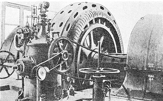
The water wheels selected for the Kern River No. 1 plant are of the impulse or tangential type. There are eight wheels installed, two for each of the four generators. The two wheels for each unit are overhung, one on each end of the generator shaft, the unit being of the two-bearing type. The water is projected onto the buckets of the wheels through deflecting nozzles of the needle-valve type mounted at the end of the 28-in. branch pipes. By means of these deflecting nozzles and needle valves the discharge from the tip of each nozzle can be accurately regulated without altering the form of the jet to any appreciable extent.
The wheels are designed to run at 250 r. p. m., and the two wheels on each unit are guaranteed to deliver a total of 10,750 horse-power to the generator shaft. Regulation of the wheels is obtained by means of self-contained oil-actuated hydraulic governors of the Escher-Wyss type, working under 125 lbs. pressure. The rotary oil pump immersed in the oil reservoir of each of these governors is operated by a Morse silent-run ring chain driven from the generator shaft. The governors act on the nozzles and deflect the stream off from, or onto, the buckets of the wheel as the load on the generator is decreased or increased. The governor for each unit is placed midway between the two nozzles and is connected to a common rock shaft which, in turn, actuates the two nozzles by means of rocker arms. These shafts are below the main floor and are accessible through a longitudinal shaft alley or tunnel 5 ft. wide and having a clear head room of 6 ft. 9 ins. The nozzles are equipped with needles for adjusting the size of the stream by hand. For convenience in construction and to permit of balancing them for backthrust, the needles are straight-backed, running through a guide sleeve of their full diameter into a balancing chamber supplied with water from the pressure side. The needle then reduces to a steam and passes through a second stuffing box, beyond which the control links are attached. The needles are torpedo-shaped, being 8 ft. long, 12 ins. in diameter at their full diameter and 8 1/2 ins. in diameter at the stem. The tip is about 25 ins. long and is carried down to a blunt point on straight lines. The needle is operated by means of a hand-wheel on the main floor, the wheel stand also supporting a pressure gauge connecting with the nozzle and the two pipes connecting the two sides of the nozzle body with the balancing chamber of the needle. Each nozzle throws a jet 7 5/8 ins. in diameter at full opening.
The nozzle casting is bifurcated, the design being adopted to permit of bringing the needle stem out without offsetting the nozzle as is done in other types of deflecting needle nozzles. The strain on the ball-joint bearings is equalized in this construction. The nozzle is a heavy steel casting, the Y portion weighing 15 tons. A counterbalancing plunger is located at the lower end of each operating lever below the nozzle. The needle stems and part of the tips are of steel. Some cast-iron tips have, however, been supplied and it is expected that they will wear as satisfactorily as the steel ones.
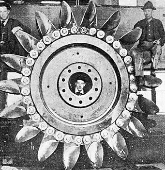
Each of the revolving elements of the wheels is 9 ft. 8 ins. in diameter, and consists of a cast-steel rim to which are bolted 18 bronze buckets. These buckets are 27 1/2 ins. wide and are not radically different in form from modern buckets used elsewhere on the Pacific Coast, being in general of an ellipsoidal shape, with a straight front wall and a dividing wedge that dips down toward the front of the bucket. The housings of the wheels are of cast iron with graceful lines, and where the shaft enters are fitted with compound baffle plates or water guards to prevent water escaping from the housing. The mechanical and hydraulic design of these wheels was carefully checked by the engineers of the Edison Electric Company before the manufacturers were allowed to proceed with their construction. The combined moment of inertia of the revolving element in the two water wheels and generator of each unit is W R2 = 1,800,00 lbs. ft.2, by means of which regulation at too per cent load variation is obtained within less, than 8 per cent when the units are carrying so per cent overload, and within less than 8 per cent variation of speed when running at normal load. The guarantee requires that the water wheel proper shall develop an efficiency at rated load of 82 1/2 per cent, which guarantee is to be substantiated by tests conducted by the company.
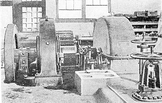
GOVERNORS.
When the governor arrangement for the water-wheels was designed, the leading idea was to have each turbine with its respective governor form an independent unit. Although the available operating water pressure of 370 lbs. from the force main is ample to operate governors, it was preferred to substitute oil pressure. This precaution is fully justified, as long years of experience in operating hydraulic governors has proven that the safety is rather questionable, and the wear and tear of the parts of regulating valves causes a constant expense for repairing and replacing parts, which necessitates shutting down the respective units. It was also deemed preferable not to feed the governors with oil pressure from a central system, but to make each governor absolutely self-contained. The oil pressure used is 125 pounds per sq. in. Special attention was paid to the safe operation of the units, eliminating- from the beginning any tendency to run away. For this purpose, the arrangement of the generator, as well as the exciter governor, was made in such a manner that the jets will be automatically deflected from the buckets whenever the oil pressure in the governor should fail.
The weight of the two deflecting nozzles for each unit is partly carried by a hydraulic balancing piston placed midway between the nozzles, which receives water pressure directly from the force main. The governor arm connects by means of a link to a common rock shaft, which, in turn, actuates the two nozzles by means of rocker arms. The design of the connection is such that as soon as the oil pressure in the governor fails, the nozzle will lower on account of the unbalanced weight, and thus deflect the jet from the buckets. The same result is accomplished with the deflecting hood of the exciter wheels, which is connected to a hydraulic water piston, tending always to insert the hood and thus deflect the jet. Each governor is driven by a Morse silent-running chain from its wheel shaft. The connections between the operating pistons and the deflecting nozzles or hoods consist of levers, pins, links and shafts. The use of gears or racks has been avoided, thereby preventing jars which would result in lost motion and wear and tear. Attention may also be called to the fact that all constituent parts, as well as all accessories, are attached or combined with one main casing, the advantage being that each governor can be assembled and thoroughly tested in the factory, and shipped completely assembled to its final destination. The main casing contains the main operating cylinder with piston and mechanical hand-regulating device. The oil pump is attached to the casing and immersed in the oil reservoir. It is of the rotary type, having no valves which are often the cause of failure of oil pressure. The main pump shaft also carries the bevel gear which drives the fly balls operating the pilot valve over the regulating lever. The pilot valve is self-contained between opposing pressures, and any reaction upon the fly balls is eliminated. It is evident that this is a principal condition for exact regulation. The pilot valve distributes the oil pressure in the regulating cylinder. The motion of the regulating piston is reversedly transmitted to the regulating valve by means of a combined compensation. The leverage of this compensation is adjustable, so that the governor may be set for any load-speed characteristic, from 16 per cent to absolutely constant speed. The governors are equipped with four regulating devices which can be used at any time. 1. Mechanical hand regulation (without oil pressure). 2. Automatic regulation with fly balls. 3. Hand regulation with oil pressure (fly balls disconnected by a clutch coupling inserted between pump shaft and fly ball shaft). 4. Hand regulation with oil pressure and electric motor operated from the switchboard. (Synchronizing attachment.) The exciter governors are of similar design, except that they are not provided for electric hand regulation. There are two exciter units, each being of the two-bearing type, with an impulse water wheel on one end and a heavy flywheel designed to give the unit close regulation on the other end of the shaft. The exciter wheels are operated from stationary needle nozzles, the needles being of the same straight form used on the main wheels. Regulation is obtained by oil governors of the Escher-Wyss type, which operate stream deflectors that are pulled up into the stream from below as the load on the unit decreases, thus deflecting a part or all of the stream into the tail race. The exciter wheels are of a construction similar to the large wheels, having 20 bronze buckets 9. ins. wide bolted to the rim of the runner. All the water wheel equipment mentioned above was supplied by the Allis-Chalmers Company. The Lombard Governor Company has furnished for the plant one of its type N governors for operating one of the main units and a type Q governor for one of the exciters. These governors arc of the vertical oil-pressure type and the order includes the necessary reservoirs, pumps, etc. The Edison Electric Company has used Lombard governors in its other hydroelectric plants and is desirous of determining the relative performance of the two types of governors in its Kern River No. 1 plant.
GENERATORS.
The main generators are of General Electric manufacture and have a rated output of 5000 kilowatts each. The stationary armature is bar-wound for 2300 volts, three-phase, 50-cycles. Each main unit is provided with two 16 in. x 48 in. babbitted bearings, each fitted with six oil rings. In the pedestals the oil is cooled by means of water coils. Each bearing also has in its lower portion a number of small openings which are connected to a triplex motor-driven pump, capable of circulating the lubricating oil under a pressure of 1000 lbs. to the square inch. The generator shaft is flared out at each end to form a flange to which is bolted the wheel disk. The shaft is also enlarged at the center to carry the cast-steel pole rim and spider. This latter is a single casting weighing 26 tons. The pole pieces are wedged to the exterior of this rim. The exciter units are standard 225-kw, direct-current machines, generating at 125 volts, flat compounded, running at 430 r. p. m., and have ordinary self-adjusting bearings. Sufficient space has been left between the two exciters to permit the installation of a large induction motor at some future time if it should be found necessary. This motor would be designed for good speed regulation and arranged so that it could be connected by means of a pair of clutches to either of the exciters.
OUTPUT OF THE PLANT.
The normal rated output of the Kern River No. 1 power plant is 20,000 kilowatts. The machinery is tested to operate under 50 per cent overload for peak load service, thus making the maximum capacity of the installation 30,000 kilowatts.
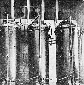
TRANSFORMERS.
The station contains 13 50-cycle, 1667-kw oil-filled, shell-type oil-circulated one-phase transformers in boiler-iron cases. These transformers are grouped in four banks of three each with one spare to receive power at 2300 volts delta from the generators, and to supply it to the line at 75,000 volts Y. Taps are also provided for the intermediate voltages of 56,250 and 37,500.
These transformers, instead of having internal water cooling coils, are so built that when the oil is supplied to them under a slight pressure, it will automatically distribute itself throughout their windings and return itself by gravity to the waste pipe. The piping and connections for this circulation, which are placed in the basement of the power house, consist of a 4-in. supply line, a 6-in. return line, and a 4-in. waste. These principal pipes are placed in a tunnel 7 ft. 9 ins. wide and 11 ft. high, extending the length of the building.
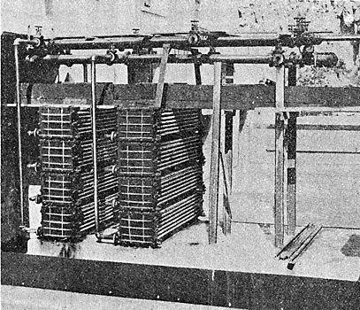
The oil coming from the transformers enters a receiving drum from which it is drawn by two 5-in, centrifugal pumps, driven by 15-hp variable-speed, shunt-wound, direct-current motors. Either pump can supply oil to the entire equipment of transformers in an emergency. These pumps force the oil through a set of boiler-tube coolers, set over the tail race, consisting of a series of 2-in. pipe, so ft. long, made up in four sections containing 1008 tubes, and having a total area of 4500 sq. ft. Only two of these sections are at present installed. From these cooling coils the oil returns to the pressure line from which it is supplied to the transformers. This system has been carefully laid out with strainers, by-passes and other auxiliaries so that the entrance of any foreign substances into the oil will not cause trouble. As the system is under pressure from the time the oil enters the pump, any leakage will be outward and there will be no possibility of water leaking into the oil, as is the case where the water coils under pressure are placed in oil-filled transformers. The oil is specially refined. Another advantage of a system of this kind is that the cost of installation is somewhat less than for a similar installation using water cooling. Water for the cooling sections is by-passed from one or both of the exciter tail races into a flume built across the top of the coolers.
ELECTRIC DETAILS OF STATION.
The generator leads pass through ducts, under the station floor, to the generator switches, and from thence to the low-tension side of the transformer banks. The station is not equipped with a complete 2300-volt bus-bar system. There are, however, motor-operated oil tie switches placed between adjacent machines and equipped with double-throw switches in such a manner that in case of necessity any generator can be transferred by means of this transfer line to any single transformer bank, or in case of absolute necessity, run in multiple with some other generator on a single transformer bank, or, if desired, the entire station can be tied together by means of this transfer bus and operated as a single unit.
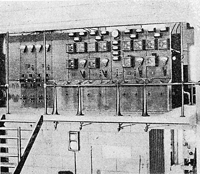
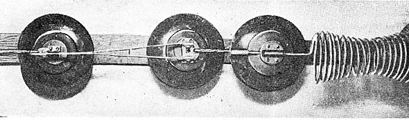
The transformer banks connect on their high-tension side through knife-blade switches to a single bus-bar, which is sectioned in the middle. The two outgoing transmission circuits are tapped off this bus-bar between adjacent transformer banks through motor-operated oil switches. These switches are remote-control, non-automatic. By use of them and the section oil switch, all high-tension power switching can be handled without the use of air-break switches. At the same time, the investment for high-grade switching is reduced to a minimum. The 2300-volt oil switches are installed in cells with concrete barrier walls and tops. The disconnecting switches for them are also separated by barrier walls where possible. The 75,000-volt oil switches are not only installed in concrete cells in accordance with standard practice, but each of them is enclosed in a separate concrete room containing no additional apparatus except lightning arresters. The control switchboard is mounted on a gallery overlooking the machine room. It is built of black slate and is a combination bench and panel board, consisting of nine divisions. The first panel on the left controls the station auxiliaries, the feeder for which is taken off the two center sections of the 2300-volt bus through solenoid-operated oil switches and then through two solenoid-operated oil switches to the panel. The second and third panels are equipped for handling the exciter circuits, and each is provided with a Thomson Astatic ammeter, a voltmeter and two single-pole, double-throw knife switches for connecting the exciter to either of the two exciter buses. The panel also has two double-pole, double-throw switches for connecting the exciter bus to the station lighting circuit and to the operating buses which control the oil-switch motors, the lamps on the control board and other auxiliaries. Panel No. 4 is blank, while Nos. 5, 6, 8 and 9 are generator panels. Each of the latter is equipped with three Thomson ammeters, a field astatic ammeter, a curve-drawing ammeter, a curve-drawing voltmeter and a curve-drawing wattmeter. The seventh panel is the auxiliary feeder, bus-sectionalizing and station panel. It contains a synchronism indicator and two voltmeters on the synchronizing bus, an ammeter on the ground circuit and an ammeter on the auxiliary feeders. The bench of the switchboard has controlling switches with red and green signal lamps for each of the four generators, and there are also provided control switches for each of the two 2300-volt feeder switches, for the switches on the 2300-volt bus sections and for the 75,000-volt outgoing line switches. The base of each generator bench panel has one governor control switch and a double-pole, double-throw control switch for operating the two 28-in. valves on each water-wheel unit. On the six-panel rear switchboard are mounted five Thom son polyphase watt-hour meters, break switches and disconnecting switches on the field circuits. A curve-drawing frequency-registering meter, driven by a 1/4-hp motor is also installed. All of the electrical equipment in the station, including generators, exciters, transformers, lightning arresters, oil switches, switchboards, etc., was supplied by the General Electric Company. The high-tension wiring is run in 4-ft. square ducts throughout, no open wiring being permitted except connections from transformers to the wall through their disconnecting switches, and from the lightning arresters disconnecting switches to the lightning-arrester banks. The lightning arresters are of multiplex type, consisting of alternate carbon spark-gaps and resistance. The circuits are equipped with choke coils, consisting of 20 turns, of hard-drawn copper. The lightning arresters are, as stated above, mounted in concrete wall cells, and are so completely isolated from each other by the intervening main-line ducts that an arc starting on any single arrester could not by any possibility be transferred to a second bank. The leads, after passing the choke coils and taps for the lightning arresters, pass out of the south wall of the building through rectangular openings located immediately below the eaves. To prevent the drip from the long run of roof from falling on the wires, a gutter extends for a few feet across the roof above each entrance. From the eaves of the building, the leads converge on to the first tower of the transmission line.
TRANSMISSION LINE-ROUTE.
From the power house the transmission line runs in as near as may be a straight line to the mouth of the Kern River Canyon, 2 1/2 miles distant, where it sweeps off to the left across the Cottonwood Hills, and then takes a due south course across the edge of the Bakersfield plains. The line then enters the mountainous section through Tejon Canyon, follows across the end of Castaic Lake, and crosses the Coast Range divide immediately above German Station.
This is the steepest portion of the transmission line, as the drop from the top of the hill to the road below is over 1000 ft. in 3500 ft. From here south the transmission line follows the waters of Piru Creek and its tributaries, the character of the country changing gradually from low, rounded hills with grassy slopes, to deep narrow gorges walled with precipitous shale cliffs capped with sandstone ledges.
A section here of about 5 miles involved very difficult work. Heavy angles, both vertical and horizontal, were necessary in a district where no permanent wagon road could be maintained, and where the tower footings were mostly in loose shale. One U-bend of the river was crossed by means of a 2250-ft. span between the main supports, guided by an entirely unloaded tower at the bottom of the sag. This heavy work was mostly executed in the middle of winter to the considerable disadvantage of the work. Leaving the Piru Canyon, the line passes in an almost straight line across about 15 miles of rocky land covered with scattered oaks and chaparral. After reaching the last crest of this district, the line falls away rapidly to the open country surrounding Newhall. Across this entire district it was necessary to construct a permanent wagon road to haul supplies and Hermit of patrolling the line during operation. The maximum grade facing the heaviest haul was held down to 10 per cent, whereas the maximum grade in the opposite direction was allowed to become 20 per cent in one special case. The ruling grades in both directions are much lighter, not averaging over 5 per cent. One bridge having two 48-ft. spans was constructed at the head of Violin Canyon (Palomas) to avoid making an extensive fill. Piru Creek, which is subject to extreme floods on occasions, was crossed by a number of fords so located as to be readily repaired after freshets, it not being considered desirable to maintain a permanent wagon road in this locality. In the Newhall district, the line crosses the San Fernando Mountains directly west of the long tunnel on the Southern Pacific. Beyond this point it is in sight from the railroad track most of the way to Los Angeles, and throughout the greater portion of the route the line is erected in the open country, so that in case of necessity the line can he repaired without excessive delay.
|