[Trade Journal]
Publication: Electrical World
New York, NY, United States
vol. 52, no. 22, p. 1171-1174, col. 1-2
German 50,000-Volt Transmission System.
T0 supply the city of Munich with additional electrical energy, and to run in parallel with the several existing municipal steam and hydraulic plants, a new municipal hydro-electric plant has recently been completed.
It utilizes the water of the river Isar in Moosburg, where three 1887-hp, double twin turbines are installed. Energy is generated at 5000 volts, but the e.m.f. is increased to 50,000 volts for transmission over two parallel circuits to the substation near the city of Munich, where the e.m.f. is decreased to 5000 volts for distribution.
This plant, known as the Uppenborn station, being the latest of German hydro-electric undertakings, possesses many novel features, particularly on the electrical end.
Thirty-three miles below the city of Munich the river Isar makes a bend, which is cut off by a head and tail race canal about 2.5 miles in length, giving a net fall of 28.1 ft. at low water and 24.8 ft. at high water. Permission was given to draw 2500 cu. ft. of water per second during 207 days, while during the remainder, including the dry season, only 1070 cu. ft. is available.
Just below the junction of the head race and the river a dam was thrown across the river at about right angles. For this purpose the width of the Isar was increased from 225 ft. to 619 ft. On the opposite end from the intake is a spillway, 328 ft. long. Adjoining the spillway is a fish passage 6.5 ft. wide, built up in steps. Next to this are the sluice gates for regulating the head. They are divided into four sections, each 55.7 ft. wide, three of which are separated by concrete pilasters, while the fourth is separated by a lock 26.25 ft. wide for passing boats, etc. This lock, having two mechanically operated swinging gates on the up-stream end, is about 150 ft. long. The bottom has a slope of about 2 per cent. It is made of concrete covered with planking.
The sluice gate passages adjoining the lock are subdivided into two sections by a removable guide, for the purpose of giving free passage for floating debris, etc. The two passages near the intake are divided into three sections, and the guides here, for the sluice gates, are stationary.
Each sluice gate is divided into two sections, one upper and one lower. They are, however, not of the same size, the lower being the smaller, thus enabling the sections, due to the hydrostatic head, to be operated by the same amount of power. Two such sections, or one gate, can be lifted by a three-phase, 10-hp motor in 10 minutes. When operated by a hand windlass with a ratio of 1:2800, 50 minutes are required to lift one section. On the down-stream side of the gates, resting on the concrete piers, is an operating gallery of structural steel.
The bottom of the intake to the head race is about 7 ft. above the bed of the river, thus preventing foreign material, such as gravel and sand, from entering the head race. As this provision cuts down the depth of the water to 4.9 ft., the width of the intake was made 125 ft., thus giving a velocity of 3.9 ft. with a friction or head of loss of 4 in.
This intake passage is divided up by a massive concrete pier, and in order to further reduce the size of the sluice gates they are subdivided into four sections by structural steel sluice guides. Each gate is divided in two parts and operated in the same manner as those described above. At the side of the dam and intake is an attendants' house, which contains also a transformer for supplying energy to gate motors. On the other side of the intake is a lock, similar to the one mentioned, for passing boats into the head race.
The head race canal is 1.3 miles long, and is built with a slope of 1 in 3000 for a calculated velocity of 4 ft. per second. It is 54.5 ft. wide on the bottom, with side slopes of 1-to-1.5. Under ordinary conditions the depth of the water is 9.2 ft. Throughout the greater part the sides of the canal are finished off in embankments, which, at the highest point, are 16.5 ft. above the natural ground.
At a low point the head race crosses a creek which is passed underneath through two culverts.
GENERATING PLANT.
The power house lies across and at right angles to the head race, which is here 175 ft. wide. At one end of the power house is a lock for passing boats and a fish way, similar to those at the dam. At the other end is a sluice gate and passage for letting off the head race water into the tail race; the latter is 1.1 miles long. Some difficulty was encountered during the excavating, because part of the work runs through marshy land.
At an angle of 72 deg. to the flow of the water to the turbine chamber, and in front of the sluice gates, are racks built up of 2.25-in. x o.25-in. bars, spaced with a clearance of 1 in. The sluice gate for each turbine is 11.5 ft. high and 24 ft. wide. It is divided vertically into three sections, which can be interconnected for motor operation.
| |||
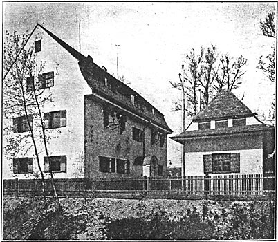
| Fig. 1. - View of Power House at Uppenborn. |
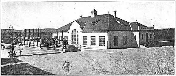
The sluice gate seen foremost in Fig. 1 is 14.8 ft. high and 13.1 ft. wide, and its purpose is for emptying the head race as above indicated. On the other end of the sluice gates is the gate for the lock; it is 26.25 ft. wide and 16 ft. high, and is lowered when the water is left off. All sluice gates, with the exception of the latter, can be motor-operated. On the down-stream side of the gates is a gallery from which they are operated by hand.
The turbine chambers are located between the gates and the generator room, the roof being flush with the street and made of reinforced concrete. There are installed three twin inward-flow Voith turbines, mounted on a horizontal shaft, each having an output, with a water consumption of 785 cu. ft. and a head of 26 ft. of 1887 hp at 150 r.p.m. Each twin turbine has its own draft tube; the two of a complete unit join into a single draft tube, which is part of the foundation and discharge into the tail race.
During the greater part of the year there is surplus water, to utilize which a 224-hp twin turbine, consuming too cu. ft. of water per second, making 300 r.p.m., has been installed. The generator of this turbine is a three-phase, 5000-volt, 50-cycle machine, designed for an output of 210 kw at a power factor of 0.9. To the unit there is coupled a 110-volt exciter. The operation of this set is kept independent from the remainder of the plant, as it supplies energy for the city of Moosburg. However, provision is made so that in case of emergency it can be joined in parallel with the rest of the plant, as will be seen below.
The regulation of each of the main turbine sets is accomplished by an oil-actuated, hydraulic governor, located in the generating room. The oil is supplied at 295 lb. pressure by pumps operated from the turbine shafts. The oil piping of the different pumps is interconnected so that one may assist another. For synchronizing the generators the governors are equipped with small motors controlled from the main switchboard.
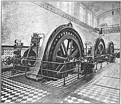
The turbine shafts are rigidly coupled to the shafts of the three-phase alternators, which are of the revolving-field, 5002-volt, 50-cycle type. With unity power factor the output of each generator is 1400 kw. Overhanging on each shaft is mounted a 17.5-kw, 110-volt exciter.
To accommodate the type of turbine generator installed the floor had to be placed about 21 ft. below the ground level, which is about 3.5 ft. above the high-water level in the tail race, thus placing the bottom of the generator pit some 6 ft. beneath the high-water level. To prevent seepage from entering the generator pits, and also the trenches for the generator leads to the switchboard, they are lined with steel plates. For the same reason, the generator leads are taken off from the upper part of the armature and passed through a column to the trenches leading to the switchboard.
The generating and switching rooms are housed under a common roof. The former is 103.3 ft. long and 26 ft. wide. In order to give the generating room a pleasing appearance, a ferro-arched ceiling is built up under the roof truss, 38 ft. above the floor level. The whole room is kept in light color, and well illuminated. The floor and wainscoting are tiled.
SWITCH GEAR.
The three main generators feed energy into one busbar system, connected at each end to transformers. Between the junctions are sectionalizing switches and on both sides of each are cut-out switches, thus keeping the two outgoing lines to Munich entirely separate. All switching is done on the 5000-volt side, there being no high-tension busbars.
For each outgoing line there is one three-phase transformer of 2000-kva rating for increasing the e.m.f. from 5000 volts to 50,000 volts. They are of the Siemens-Schuckert, oil-insulated, water-circulated type. By using 60 cu. ft. of cooling water pet hour, with the transformers under full load, the temperature of the oil surface is 95 deg. Fahr. above that of the incoming water. The efficiency at full load is 98 per cent. The ohmic resistance drop is 0.95 per cent, while the impedance voltage at full load current is 3.5 per cent.
| |||
| Fig. 3. - View of Generating Room, Uppenborn. |
The secondary windings of the transformers are split up into sections with the leads brought outside, so that they can be readily changed from star to delta connection for giving a 25,000-volt transformation if desired.
The transformer casings are made of steel plates, and rest on rollers and tracks, whereby they can be shifted to the generating room and there handled by a 16-ton overhead crane for repairs Each transformer, when filled with oil, weighs ii tons.
A novel feature in connection with the transformer, and of especial value to hydraulic plants, is the utilization of the circulating water of the transformers for heating the various rooms of the plant.
The water for cooling the transformers, as well as that the water-jet grounders and for drinking purposes, is supplied by a 5-hp centrifugal pump, which delivers to an elevated tank. The pump works automatically between the limits of 45 lb. and 75 lb. Use is made of a 3-hp auxiliary pump when the cooling water of the transformers is utilized for heating purposes. Another pump removes possible seepage.
In front of the switchboard is a controlling bench from where the generator room is readily overlooked. It contains all levers and wheels on the flat surface, while the instruments are mounted on the incline. From this desk the attendant starts the turbines by means of the motors on the sluice gates. Moreover, the field and speed regulation, synchronizing as well as loading the generators, is done from this point without the attendant losing sight of the generating room.
The switchboard is made up of seven panels, four for generators and three for the outgoing lines. All are of the wagon panel type of the Allgemeine Elektricitdts Gesellschaft, consisting of a small carriage resting on wheels upon the steel framework of the switchboard. The advantage of the wagon panel system is that the panel, with equipment, can be readily withdrawn for inspection and repair. The electrical connections are made by copper clips on the back of the carriage, which is done by sliding in the wagon panel. Each generator panel contains an oil-switch provided with an overload and reverse-current time-limit relay, which can be operated by a hand wheel on the panel or by a pilot switch on the controlling bench. The two series transformers for the relays and one for the ammeter are also placed in the carriage, while the switch indicators are located on the controlling bench. There is also a small three-phase transformer for the synchronism indicator and one for the wattmeter; the instruments themselves are placed on the controlling bench.
The individual equipment of the carriages are disconnected by small switches placed in a row on the switchboard front.
Each of the transformer panels contains an oil-switch with an excess-current cut-out and a wire break relay; three series transformers; one ammeter with its transformer; one potential transformer, and two dry elements for the wire break relay.
In the power house, as well as the substations, there are very extensive systems for protection against lightning. The, equipment in the power house is as follows: For direct lightning strokes there is placed at each phase-lead a horn-gap of 9/16 in., connected to large water rheostats, located in an annex of the power house. In the upper floor of the switching rooms are four choke-coils connected in series, each preceded by a horn-gap. Between these and the transformer is a coil known as the generator choke-coil, which is also provided with a horn-gap. All of the gaps for each phase lead (2.25-in. setting) have a common ground. To the grounding device is connected an oil rheostat to prevent the generator current from following the lightning stroke. To take care of light surges, water-flow grounders are installed.
To equalize the pressure between the phases, there are three horn spark-gaps connected in "star" to the middle point of the transformers.
It might be of interest to state that the water-flow grounders are designed to carry off from 0.1 amp to 0.15 amp, according to the chemical composition of the water. This means that three-phase grounder leads off 9 kw, and the power for four grounders amounts to 36 kw, which is less than I per cent of the power to be transmitted. The water is supplied by two centrifugal pumps.
The horn-gaps, of which there are five per phase lead, are spaced 8 in. apart. The others of the different phase leads are spaced 6 ft. apart, between which are double asbestos partitions 7.8 ft. high. As they are located on the upper floor of the switching rooms, the roof and roof truss over the horn-gap room is lined with cork-plates covered with an incombustible material.
As stated, the 210-kva generator, supplying 5000 volts for the city of Moosburg, is, under ordinary conditions, operated independently of the rest of the plant by means of sectionaling switches in the busbars. The energy is conveyed by means of a cable running along the head race. At the attendants' house, near the dam, a tap is made to feed a 30-kw, 5000-volt to110-volt transformer for operating the sluice gates.
All station insulators for 50,000 volts are made up of three corrugated cylindrical porcelain sections, held together by a mechanical screw coupling. The height over all is 11.5 in.; the diameter of the lower section is 5.5 in., and that of the remainder, 3.75 in. The design is such that the total porcelain thickness between the metal couplings is 2.25 in., while' the surface leakage path is 23 in. The corrugations have the effect of making the high pressure noticeable by loud hissing dark discharges, but without measurable loss. These insulators are placed at least 20 in. apart, while those carrying ground connections are spaced not less than 12 in. apart.
 |
| Fig. 4. - Wall Outlet of 50,000-Volt Transmission System, Uppenborn. |
The high-tension wall-outlets on the main as well as on the substations are of the design seen in Fig. 4. An outlet consists of two concentric corrugated poreclain bushings cemented together, which in turn are cemented in the bell-shaped end of a tile cylinder 16 in. in diameter. As the radius of the line conductor is only 3.5 mm., it was thought advisable to increase its diameter artificially by placing a brass tube 85 mm (3 3/8 in.) around the conductor, thus cutting down any arcing effect due to brush discharges. Although the distance between line and ground is reduced, the arcing effects are no more noticeable.
TRANSMISSION SYSTEM.
The transmission system is 32 miles long, and calculated to transmit 4000 kw at 50,000 volts, for which purpose two separate transmission lines were installed. The conductors consist of a seven-strand cable, 16 sq. mm in cross-section, and spaced 4.6 ft. on a leg. Under normal operation both circuits are alive, and under this condition the total resistance drop is about 1100 volts and the reactance drop 43o volts. The power-factor at the power house is 0.95, while at the substation it is unity. This difference is due to the charging current.
 |
| Fig. 5. - Types of 50,000-Volt Insulators. |
As will be seen in Fig. 5 there are two different kinds and manufacture of line insulators; both are of the three-petticoat, two-piece type glazed together in the manufacture. The insulator shown at the right-hand is 9 in. high, the head being 8.75 in. diameter. The other is 10.25 in. high, the head being 9.5 in. in diameter.
| |||
| Fig. 6. - Transformer Station and Lightning Arrester House, Hirschau. |
Before the contracts for the transmission structures were let, tests were conducted on (1) wooden A-frame structure, (2) steel tube poles, (3) Mannesmann tube poles, (4) latticed tower of angle iron, (5) I-beam A-frame.
The following table gives a comparison of the tests on the above structures, together with the price in marks. The structures are tabulated successively, as above numbered, and are expressed in the metric system and serve for ready comparison:
 |
It will be noticed that the wooden structure was not favorable, especially as the line passes through marshes, and the life of a wooden structure is short. The I-beam structure outstripped the others regarding safe load and price, which is the reason why these poles were adopted.
The standard poles are 23 ft. high to the lower insulators; the standard spacing is about 165 ft., the two parallel poles are spaced about 13 ft. apart. They are imbedded in concrete blocks about 5 ft. deep. Each pole is made up of two 5.5-in. I-beams; for present conductors 3.5-in. I-beams would have sufficed. but because in the future new plants will be put on the line heavier conductors were employed.
There are a total of 2260 towers, which were erected by two gangs, each consisting of 4o men, capable of erecting, on the average, 20 towers per day. As nearly the whole course follows the river Isar, all of the material was conveniently transported on boats.
There are only a few special structures throughout the whole line. Wherever the transmission line crosses a telephone line higher poles are chosen, no guard or net wiring is employed. In one instance a special lattice girder construction was erected for crossing the State telephone system. The line crosses the Isar three times, and at these points special angle-iron lattice constructed towers are made use of to carry spans of 365 ft. For these spans, instead of copper, bronze conductors of 29 sq. mm were used. The poles are grounded by a 12-fn. x 12-in. plate; all poles are interconnected electrically by an iron wire.
| |||
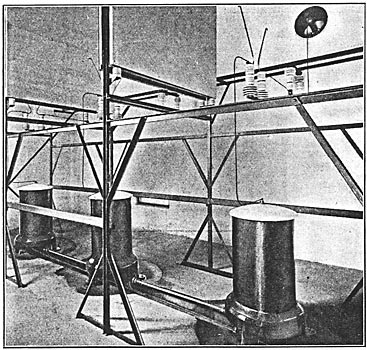
| Fig. 7. - Horn Gas and Rheostats, Lightning Arrester House, Hirschau Substation. |
| |||
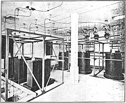
| Fig. 8. - Lightning Arrester Equipment, Hirschau Substation. |
The whole line is transposed three times, thus dividing the line into four sections, to nullify the electrostatic and inductive effect on the telephone line. The last transposition brings the phase leads into their original position.
Midway between the power house and Munich, at Achering, there is a lightning-arrester station, through which the circuits pass. This station is divided up into two separate rooms, one for each circuit. Here are located three horn-gaps with 2-in. setting; they are 6 ft. apart, separated by double asbestos partitions. Each phase lead is connected to a 5000-ohm rheostat submerged in oil and then grounded by plates connected to the ground wires of the towers. Section switches are placed between the lines and horn-gaps, so that the latter can readily be cut out. Line section-switches are placed at intervals of 1 km in order to facilitate the localization of faults.
The four sections were watched by four patrolmen, each covering twice daily eight miles. After a quarter year of operation, it was found more economical to replace the four patrolmen by two men mounted on motor-cycles. When extra men are needed they are called in by telephone and arrive on motorcycles.
The lightning-arrester station has two telephones, one for each transmission line. They are carried on the towers of the transmission line about 3.5 ft. below the lowest conductor. The telephone lines are transposed every 650 ft. to counterbalance any inductive effects.
SUBSTATION.
Energy is received at the end of the line at the Hirschau transformer station at about 48,00o volts, the e.m.f. being then transformed to 5000. The lines enter the substation with protection devices similar to those at the power house, and feed
·
·
[Missing text]
·
·
