Early Suspension Type Insulators
July - December 1910
|
[Trade Journal] Publication: Stone & Webster Public Service Journal Boston, MA, United States |
|||||||||
|
SUSPENSION TYPE INSULATORS.
By A. S. KALENBORN.
The writer discovered recently, on a trip to Donner Lake, California, some of the original insulators used on the pioneer telegraph lines of the West. With the development of the glass insulators such as are used on all telegraph lines today, these old ones with their supporting cross arms were thrown aside and, through the agency of fires and decay, have, at this date, almost entirely disappeared. Three different types of insulators were used, all of them "underhung." It is this fact that makes them the more interesting in their relation to the latest development of high tension insulators for power transmission. In just the same way that the original alternating current dynamo was neglected for a time, during the development of the direct current generator, so these old insulators are the almost forgotten prototypes of the modern disk or suspension type of high voltage insulators. Faraday, in 1831, constructed a generator which produced alternating current by mechanical means, and Sturgeon in 1836, by the addition of a split tube commutator, "rectified" the undesirable alternating current and obtained continuous or direct current. Until the advent of the commercial transformer, little was done ii the alternating current field, the direct current being used almost exclusively. The transformer, however, changed the line of development and, with improvements in insulation and insulators, the era of long distance transmission of power began. Oil insulation in transformers solved one difficulty, and glass, and later porcelain insulators on the lines, made the transmission of voltage up to sixty thousand or eighty thousand volts possible. With the increase of potential on these systems, there followed a corresponding increase in the size and complexity of line insulators. When for sixty thousand volts a four-part porcelain insulator, with a top shell sixteen inches in diameter, was necessary, the whole combination weighing more than thirty pounds, it was evident that the limit of the pin-supported type had been reached. The leverage on the cross arm of from sixteen to twenty inches was rather severe. Various combinations of pin-supported insulators were revised, but the disk or suspension type solved the problem of line insulators for extra high potentials. In the Transactions of the American Institute of Electrical Engineers, Vol. XXVI for 1907, two articles appeared, the first, "A New Type of Insulator for High Tension Lines," by E. M. Hewlett, and the second, "Some New Methods of High Tension Line Construction," by H. W. Buck. These new insulators were a distinct departure from anything previously used for high tension work, but in these old telegraph insulators we find their underlying principle and see again how history repeats itself.
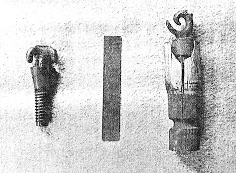
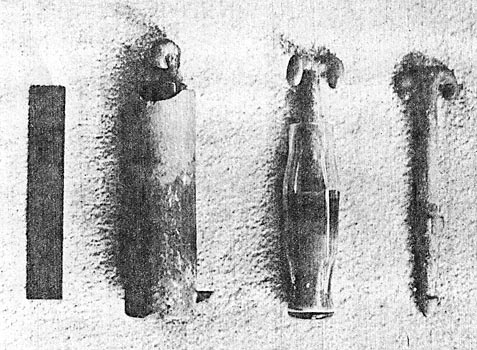
The three insulators shown in the cuts herewith depend upon three different materials for their insulation, one having wood, the second rubber, and the third sulphur and glass as the dielectric. The wooden insulator shown was formed from a single piece of hard wood, turned in a lathe, and had a cast iron hook, for supporting the wire, screwed into the lower end. This hook has a shank half an inch in diameter threaded its entire length of one and three-quarters inches, and was provided with a cast ferrule, one and one-eighth inches in diameter, and an inch long. Concentric with this inside cone into which the hook was screwed and turned out of the wood was an enclosing shell or petticoat. This petticoat is two inches in diameter and two inches deep, giving considerable creepage length. The entire insulator was dipped in bitumen or other compound, which is still evident on the parts protected from the weather. The line wire was held in place by a tie wire laid in the notch at the back of the hook. The threads on the hook were machine cut and the insulator, when new, must have made a neat appearance, though the cost, considering the insulation obtained, must have been quite high. The insulator was secured within the cross arm from below, a hole one and three-quarters inches in diameter and three inches deep being bored in the arm to receive the shank. The groove in the shank prevented the insulator from dropping out of the arm, for a wooden pin was driven horizontally through the arm engaging with the groove for that purpose. This wooden insulator was used on the line which followed the old emigrant road westward past Reno, Truckee, and through Donner Pass to the Pacific Coast, and must have been part of the system. of the old Overland Telegraph Company. This company completed a line through to Salt Lake City from California, sending its first message October 29, 1861. There was great rivalry in the building of telegraph lines in the West at this time. In 1860 the Western Union secured a grant from the United States Government of an annual subsidy of forty thousand dollars for ten years, with a quarter section of land for every fifteen miles of line built in exchange for the free transportation of Government messages to the above amount, the rate for any message being limited to $3.00 for ten words. On the line built by the Western Union in the sixties to Lake Tahoe, the second type of insulator was used. This is the smallest and simplest of the three, consisting of a double iron hook upon the shank of which a rubber thread and petticoat was moulded. The hook was heavily galvanized and was formed so as to hold the line wire without a tie. The line wire when placed in the hook, was kinked into a "U" shape, and when once pulled up was held firmly and securely against slipping. This little insulator is four and half inches over all, and has a three-quarter inch shank, threaded, so that it could be screwed into the under side of the-cross arm. Where the line ran through the forest, small blocks, a five-inch length of cross arm, were nailed to the trees by four spikes, and the insulator secured within these from below. Having been in place for nearly fifty years, the hark of the trees has nearly covered these blocks, and their removal at this time was attended with considerable difficulty. On the shank just below the thread the following words were moulded into the rubber: "Goodyear's Patent lay 6, 1851," which takes us back nearly sixty years, or to a time eighteen years prior to the laying of the first trans-Atlantic cable. In Tacoma, Washington, I discovered in '89, several of these old rubber insulators, probably a part of the line which the Western Union attempted to build in 1865 to Europe, via Alaska and Siberia. Telegraph Creek near Wrangell, Alaska, received its name from this attempt, and I have been told by some of the old prospectors who were on the Behring Sea coast above Nome, in Alaska, that they came across some of the old telegraph supplies taken up there at this time. The largest and most elaborate of these underhung insulators consists of four separate parts, a double hook for holding the wire, a glass bottle serving as the insulator, a cast iron cup for protecting the bottle and supporting it within the cross arm, and a wire or nail to keep the whole combination from dropping out of the arm. The cut shows the various parts, the six-inch scale beside them giving an idea as to the dimensions. The galvanized hook is seven inches over all in length, and has lugs or flutings to prevent it from turning, and also to enable the sulphur to grip it to better advantage. The hook being sulphured into the bottle, the two were then sulphured into the east iron galvanized cup or cylinder. Two depressions in the glass bottle served to give the sulphur a better grip, both inside and outside the bottle. The cast iron cup is two inches in diameter, one-eighth inch thick, and is six and one-eighth inches long. At the closed or upper end a boss projecting radially served the same purpose as the groove in the wooden insulator. For the wooden insulator a plain circular hole in the cross arm sufficed, but with the cast iron cup it was necessary to channel with a chisel the full depth of the hole to allow this boss or lug to enter the arm. The insulator when placed within the hole was prevented from dropping out by inserting a wire or spike through a horizontal hole bored through the cross arm immediately under the lug. The insulator complete weighs one pound, ten ounces and is seven and five-eighths inches over all in length. On the bottom of one of these cups are the words, "Brooks' Patent August 6, 1867," and on another, in addition to the above, are the initials "C. P. R. R." (Central Pacific Railroad). In the book, "How We Built the Union Pacific Railway," by Major-General Grenville M. Dodge, opposite page sixty-seven, a photograph is shown of the "Joining of Tracks, Promontory, Utah," in which can be seen a telegraph pole, the insulators on which are of this last pattern. This epoch marking photograph was taken on May 10, 1869, in commemoration of the completion of the first trans-continental railroad. These insulators are therefore true pioneers. Joining ocean to ocean in communication, they played their part on the day when transportation by rail from East to West became a factor in our great industrial and commercial development, assisting in proclaiming the driving of the golden spike, simultaneously in San Francisco and in all the large Eastern cities. And now they have increased the radius of the transmission of power by electricity, assisting in bringing the energy of the water in the far distant mountain streams into our cities and our homes for the benefit and comfort of all mankind.
|