Suspension Insulator for High-Tension Lines
|
[Trade Journal] Publication: Scientific American New York, NY, United States |
||||||||||||||
|
Evolution of the High-tension Insulator LESS than a quarter of a century ago the first alternating current power transmission line was erected in the United States. The current was transmitted at 3,000 volts, which was considered very high pressure in those days. With that beginning the development of high-tension transmission lines progressed steadily, until by the end of the century, 60,000 volts had been reached. Then, for a time, there was a halt. A serious obstacle was encountered. The development of generating and transforming machinery had outgrown the development of insulation and the former had to wait for the latter to catch up. When a new system of insulation was discovered, high tension took up the march again and there was steady progress, until, now, we have transmission lines of 150,000 volts and consider 250,000 volts not an impossibility, but a probability in the course of the next few years.
The making of an insulator may seem a very simple thing, involving merely the quantity of insulating material placed between the conductor and the support. That was the first idea, but it was soon found that insulators exposed to the weather accumulated impurities, dust and the like, so that when they became wet, they offered a path more or less imperfect, but nevertheless a path for leakage of electricity. Then more attention was paid to the shape of the insulator. It was formed with a number of petticoats so as to increase the under surface on which dust and rain would not be liable to collect. With increase of voltage the insulators became larger and larger and the petticoats more numerous until finally they became so cumbersome as to present serious mechanical difficulties in their construction and in the maintenance of the poles upon which they were mounted.
The use of higher voltages also developed other weaknesses. Glass was found too brittle and liable to break with variation of temperature. Furthermore, it was easily wetted, so that in rainy weather a film of water would form upon it. Porcelain was substituted for glass and found better in many particulars, but its chief insulating quality lies in the surface glaze. When this is cracked and it is liable to be cracked by action of the weather moisture entering the cracks will expand when frozen and rupture the insulator, resulting in a short circuit. Unfortunately when a high-tension line is short circuited, surging is set up which is liable to rupture other insulators along the line. The effect is cumulative, so that serious damage may result from one defective insulator. A search was made for better insulating material, and a number of compounds have been discovered which show greater mechanical strength, which are unaffected by temperature changes and which, being of an oily nature, are not readily wetted with water; that is, the water collects in drops rather than in a film over their surface.
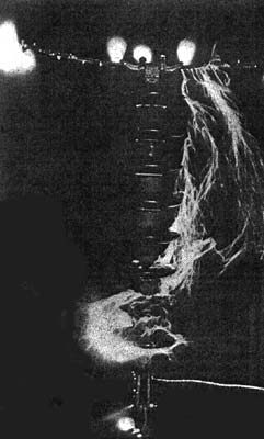
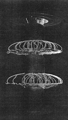
But the problem was more than one of material only. It was a mechanical problem. The pin type of insulator had been outgrown. The next development was to suspend the insulator from the cross arm, instead of supporting it on a pin. Because a flexible support can be made much lighter than a rigid one, this reduced the weight on the cross arm at once. The conducting wire could be supported at a greater distance from the cross arm than was possible before. Furthermore, a chain of insulators could be used in place of a single, large, rigid insulator. This is the type of insulation now in common use on high-tension lines, the only objection being that the line is apt to sway in the wind and might come in contact with its support. This may be prevented by proper spacing and the use of lateral guy lines also made up of chains of insulators known as "strain" insulators. Still another method is to "dead end" the conductor at each pole by means of "strain" insulators, using short loops to carry the current past the cross arm. Both the "suspension" and the "strain" types of insulators consist of disks formed with petticoats or flanges and furnished with hooks at each side, to permit of connecting any number together in a series long enough to provide the desired insulation. The series is often "graded" from a large insulator at the conductor to a small one at the support, thus reducing weight and at the same time increasing the insulating qualities of the series. The accompanying detail drawings illustrate the degree of perfection to which the present-day insulators have been developed. The constructions are the invention of Mr. Louis Stelnberger, one of the pioneers in the development of high-tension insulation, he being the first to make successfully, and on a commercial basis, high-potential insulators from a material other than glass or porcelain. It will be observed that the suspension members are imbedded in the insulator and interlaced, so that should the insulating material be shattered, the line would still be supported by a chain made up of the suspension members. Owing to the swivel form of the terminal, two or more units may be connected or disconnected in the fraction of a minute, no special tool being required to operate the connecting nut, as a plain wrench, a nail or even a piece of wire may be employed. The clamp, which is shown suspended from one of the insulators, is formed with flared ends to prevent crystallization and possible breaking of the conductor as it is swung back and forth by the wind. The disk or suspended type of insulator has become so standardized that it is used on all lines operating above 50,000 volts, and even on lines of 44,000 volts in some instances. The 10-inch disk "strain" and "suspension" insulators here illustrated have been tested to show a puncture value in oil of 150,000 volts, and of 100,000 volts when tested to dry arc value. The rain arc value is 55,000 volts, line voltage 25,000 volts and mechanical value 20,000 pounds, while the weight is not 11 pounds.
|