Niagara-Buffalo line and U-937
|
[Trade Journal] Publication: The Electrical Engineer New York, NY, United States |
||||
|
THE NIAGARA-BUFFALO TRANSMISSION LINE
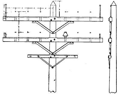
The Buffalo Power and Conduit Company, which was organized to distribute Niagara power in Buffalo, has awarded the contract for the construction of its power transmission line between Niagara Falls and Buffalo to the White-Crosby Company, of New York. This transmission line will run from the power house at Niagara Falls along what is known as the Two-mile-line road, near the tracks of the New York Central and Erie railroads, crossing the creek at Division street, and from Tonawanda to Buffalo city line it will follow the canal banks. The transmission line embodies a number of special features of construction, in view of the fact that it will carry very heavy wires, and will be subject to the high winds and storms of snow and sleet which the region in the vicinity of Niagara is subject to. The poles will vary from 35 to 65 feet in height, depending upon the contour of the ground, so as to maintain the wires as level as possible. Depending upon the height they will vary from 14 to 28 inches in diameter at the top. They will be set into the ground to a depth of from 7 to 8-1/2 feet, depending upon the height. All poles will be of white cedar, selected, shaved and painted. The pole line is intended to transmit 20,000 horse-power over four circuits, of three wires each, the three-phase system having been adopted. These circuits will be erected on two cross arms, each side of the cross arms carrying three wires, as shown in the accompanying illustration, Fig. 1. Each of these three wire sections is thus intended for 5,000 horse-power transmission.
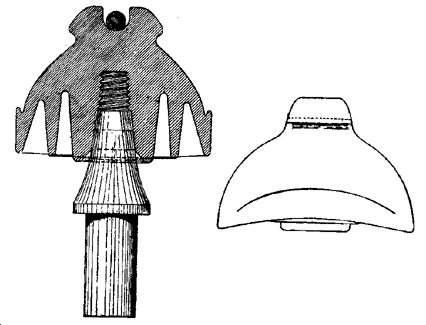
In order to make the construction as strong as possible a special form of brace has been employed, which, it will be seen, consists of a 2-1/2x2-inch angle iron, bent in one piece. These angle irons will be secured to the cross arms by two lag screws, so as to insure a tight bearing without play, a feature which could not be secured if through bolts had been used, which, in addition, would have weakened the pole to some extent. The angle iron, it will be evident, constitutes as good a strut as it does a tie, and in this respect is much superior to the usual form of straight iron brace. As the potentials carried on this line will be very high, a special form of insulator has been designed, capable of withstanding 40,000 volts. These insulators will be of porcelain, with triple petticoats, as shown in section in Fig. 2, and will be of the helmet form, as shown in Fig. 3.
The base of the helmet measures seven inches in one direction and nine inches in the other, and the insulator will be placed with the greater length parallel with the line of the wires. It will thus be seen that any water falling on the insulator will run into the grooves or brim of the helmet and drop down clear of the cross arms. Icicles which may be formed will also fall clear of the cross arms. The insulators will be mounted on 2-inch pins, and in order to increase their strength a construction has been adopted such that the body of the insulator bears for a considerable distance below the thread of the pin. This prevents the revolving of the insulator and the stripping of the thread, even with a full lateral load on the wire. The conductors, three-quarter inch in diameter, 350,000 circular mills section, will lie in the groove in the top of the insulator, and will be tied. It will be noted that the insulator is so designed as to have the same thickness of body between the top of the pin and the main conductor, as between the pin and the tie wire when in place. Special precautions have been taken to guard against lightning, and for this purpose the top cross arm on each pole is provided with a one-inch rod of double refined iron, forked at the top with a three-eights-inch groove. In this groove, or channel, barbed galvanized wire will also be run along the tops of the poles thus affording a complete protecting mantle. At every fifth pole one of the lightning arrester bolts is prolonged through the cross arm, and to this prolongation a ground wire will be attached. The ground will consist of a coil of tinned No. 6 copper wire, buried in the ground and brought up a foot above the surface, where it will be attached to the iron wire leading down from the lightning arrester pin. Iron has been adopted to lead down the poles to the grounds, as it is less likely to fall a prey to copper wire thieves. These lightning arrester pins will also act as a guard to prevent the upper wires from falling to the ground in case the insulator should break. On the lower cross arms special iron guard pins, six inches high, will be placed, which will act in the same way to catch the wire in case of a fracture of the insulator. Below the two main cross arms a third cross arm, six feet in length, and carrying six pins will be run, which will carry three circuits of No. 12 copper telephone wires. The main conductors will be transposed at five points between Niagara and Buffalo, so as to avoid the effects of induction between the circuits. The contract calls for the erection of the pole line complete with three wires by November 15.
|