General Electric Three-phase Transmission Plant at Taftville, Connecticut
GE's Standard "Oil Insulators" Were Used
|
[Trade Journal] Publication: The Electrical Engineer New York, NY, United States |
||||||||||||||||||||||||||||||||||
|
GENERAL ELECTRIC THREE-PHASE TRANSMISSION PLANT AT TAFTVILLE, CONN.
The first important application of electrical power transmission to textile manufacture has just been installed by the General Electric Company at Taftville, Conn, the power being transmitted from Baltic to Taftville, a distance on nearly four and one-half miles. It is a typical transmission by three-phase currents, in which motors of the synchronous type are used not only to operate one of the most interesting cotton mills in this country, but also the power station of the Norwich (Conn.) Street Railway. Mr. E. P. Taft, the progressive founder of the Taftville cotton industry, long ago recognized the value of the available water power at Baltic, on the Shetugket River, near to which stood a ruined mill destroyed by fire some years ago, and having secured the property with the water rights determined to utilize the power as soon as a successful plan was offered.
The Ponemah Mills are situated at Taftville, also on the Shetugket, and about three miles distant from Norwich. The original mill was operated for a nearly score of years by water power taken directly from the river, and when the new mill was erected it was found necessary to drive it from two 350 h. p. Corliss engines, the existing dam being insufficient in capacity. In these mills are manufactured perhaps the finest and most delicate cotton fabrics produced in this country. All manner of fancy weaves for special purposes, form the regular output of this mill, and the exceptional quality of the goods has kept the plant steadily at work during the dull times, even when cotton mills all over the country have been shut down. In Figure 1 are shown the relative positions of the generating station at Baltic and the receiving station at Taftville. The line is nearly four and one-half miles in length and is carried along the highway up the river, skirting its bank in places and crossing it at intervals to shorten its route.
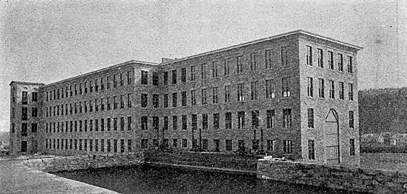
The rebuilt mill at Baltic is shown in Fig. 2. In the basement of this building are the wheel and dynamo rooms of the generating plant. The mill is of four stories, built of stone, and will presently be used, as the Ponemah Mills, in the cotton weaving industry. Four hundred feet above the mill a fine stone dam, 525 feet long, has been thrown across the river. The effective head on the turbines is 32 feet, and the water available, even in the dryest seasons, is sufficient to furnish not less than 1,500 h. p.
Fig. 3 is a plan of the basement of the mill in which the power plant is located. It will be seen that the turbines are belted to pulleys on the main line shaft extending the whole length of the wheel room and continuing through the partion walls into and along one side of the generator room. The pulleys are thrown into, or out of, action by Hunter clutches mounted with pulleys on quills, so that any or all of the wheels can be applied to driving the shafts. Similar pulleys and clutches are furnished in the dynamo rooms for throwing in or out the various machines that may there be placed.
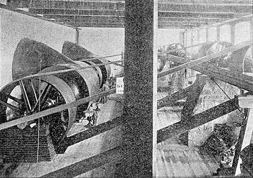
Fig. 4 shows the wheel room and the arrangement of the turbines and line shaft. There are three double 42-inch horizontal wheels and one double 27-inch wheel, the former developing 800 effective horse power each at 157 revolutions per minute, and the latter 800 horse power at 244 revolutions per minute. The belts pass obiquely upward to the pulleys on the line shaft, and the turbines are kept at speed by Schenck electric governors, which have proved themselves capable of doing very fair service. The wheel plant and shafting were made and installed by the P. C. Home Company, of Gardiner, Maine. The line shafting is supported by heavy iron girders set on stone piers and additionally braced by timbers.
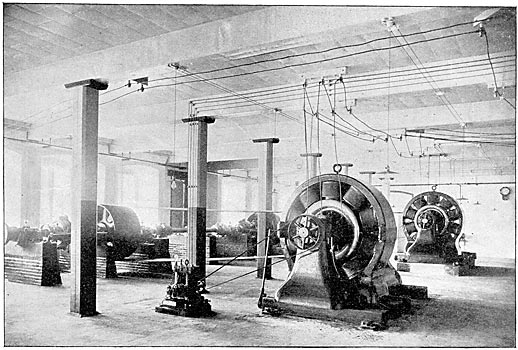
The dynamo room, Fig. 5, beside the shafting is occupied by two 250 K. W. General Electric three-phase generators, delivering current on the line at 2,500 volts. Each machine is provided with its own exciter, a 3 K. W. bipolar dynamo. The three-phase machines run at 600 revolutions per minute, and are set so firmly on substantial foundations as to run with scarcely a perceptible vibration. The driving pulleys on the main shaft are fitted with Hunter clutches, so that either machine can be dropped out without the slightest disturbance to the service.
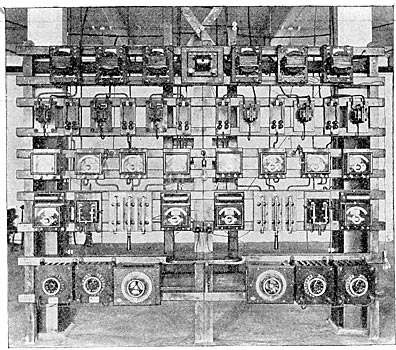
The generators are connected to a common switchboard, Fig. 6, and may be run in parallel whenever desirable. To this end the board is furnished with synchronizing appratus, the acoustic synchronizer being mounted on the face of the switchboard, and the equalizing switch being at the back. The most interesting novelties in this switchboard are the high voltage switches on the lower part of the board. These are mounted on marble bases with substantial barriers erected between the switch-blades, so that the circuit at full load and voltage may be broken without the slightest danger of arcing across from point to point. They have been amply tested and have proved their ability to cope with the trying work required of them, with the greatest ease. The generators fall into parallel easily and run as smoothly together as would a couple of railway generators. No artificial load is used in throwing them together, none having proved necessary.
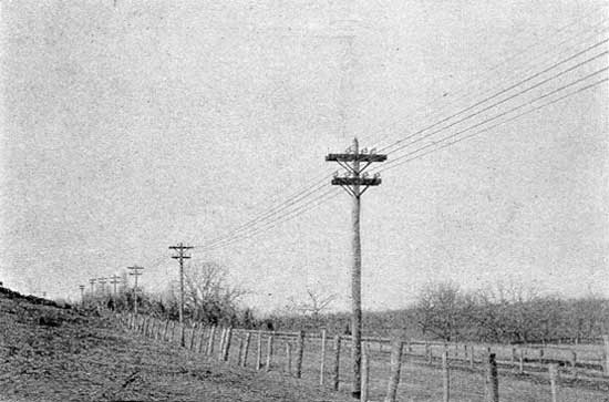
The line, a characteristic bit of which is shown in Fig. 7, is a good piece of construction work on substantial wooden poles placed 100 feet apart. The wires on the upper cross arm are of No. 0 bare copper and form the original three-phase circuit designed for the transmission. The wires on the lower cross arm are No. 0000 insulated wire, and are four in number. They were originally intended for a railway circuit, the generators for which were to be installed at Baltic to feed the Norwich Street Railway, but as the amount of copper necessary to do the work successfully appeared too great, the system was changed, a second three-phase generator and motor were added, and three of the four proposed feeder wires were utilized for the three-phase circuit. All are supported on the General Electric Company's standard oil insulators, the fourth No. 0000 wire forming a convenient relay in case of accident to any of the others.
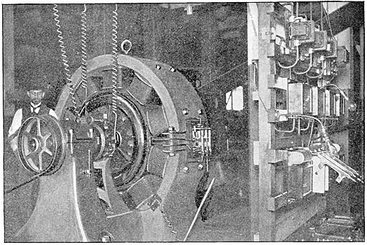
At Taftville the three-phase circuits are led into the basement of the new mill, where they drive two three-phase synchronous self-starting motors, identical in size with the generators at Baltic. These machines replace the two Corliss engines previously used. One motor, with its switchboard, is shown in Fig. 8, which also gives an excellent view of the high voltage switch before referred to. These motors are belted to the jack shafting previously · · [Missing text] · ·
|