Niagara type insulator
|
[Trade Journal] Publication: Electrical World New York, NY, United States |
||||||||||||
|
The Construction of a 150,000 Volt Transformer. BY ELLERY B. PAINE AND HARRY E. GOUGH .
As a subject for post-graduate thesis work at the Worcester Polytechnic Institute during the past year the writers have designed and constructed a 150,000-volt transformer, and as some radical changes from the usual method of transformer construction are necessary when dealing with such high potentials a short description of this piece of apparatus may be of interest. The source of supply of current for the transformer is the 30-kw Westinghouse smooth-core alternator situated in the power laboratory. This machine has a frequency of 133 cycles and its virtual voltage is 1000. Since it would not be convenient to arrange the necessary switches and circuit breakers in a 1000 - volt circuit, it was decided to reduce the pressure by means of small transformers, and in this way the supply for the high -potential transformer could be either 50 volts or 100 volts as desired, with the alternator excited so as to give 1000 volts on the line.
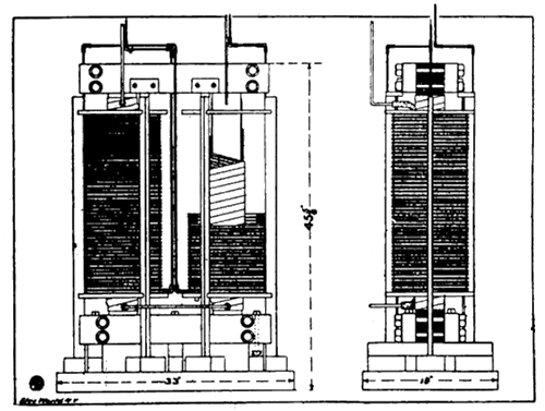
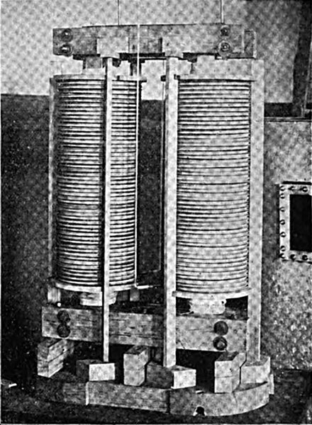
As there were ten transformers available for this purpose, and the capacity of each was 2 kilowatts, the output of the high-potential transformer was limited to 20 kilowatts. From this it is seen that the problem was to design a 20-kw transformer for a frequency of 133 p. p. s. to give 150,000 volts at the terminals of the secondary with 100 volts supplied to the primary. In working out the design the end kept in view was to produce a transformer which would give the highest insulation for the lowest first cost of materials and an efficiency sufficiently high to maintain good regulating qualities. The core type of transformer was selected for this case because that form seemed to offer better means for insulation than did the shell type, and would at the same time be easier to build. With a virtual voltage of 150,000 at the terminals of the secondary the maximum voltage to which the insulation will be subjected is 150,000 x 1.4, or over 200,000 volts, since the E. M. F. wave of the alternator is very nearly sinusoidal. With this voltage a spark will jump across an air space of about 15 inches, whence it is evident that the transformer must be surrounded by some better insulating dielectric than air. To determine what was the best oil to use for this transformer a series of comparative tests was made with different commercial oils. In making these tests an induction coil giving an E. M. F. of approximately 15,000 volts was used. From the results obtained in this way, together with the results obtained by other experimenters, it was decided that kerosene oil would be used, and it was estimated that 3" of this oil would withstand a potential of 200,000 virtual volts. To find out if the oil would be apt to take fire if it were used and sparks should pass through it heavy arcs were formed in a sample of kerosene; and in no case was the oil observed to take fire. From preliminary calculations carried through with different values of magnetic density in the core and different core areas, it was decided that a maximum core density of 8128 gausses per square centimeter should be used. The core is rectangular in form and the windings surround the two vertical legs. It is built up of ' soft iron strips 0.025 inches thick, and the over-all dimensions are 18/2 " by 39". The two upright parts are composed of strips of different widths, so that the form of cross section is approximately a circle a little over 4 inches in diameter. The actual area of cross section of iron in the core limbs is 78.7 square centimeters, so that the total Aux passing through the windings is 640,000 webers. The yoke pieces are built up of strips 4 inches wide, and the area of cross sections at this point is 92.9 sq. cen. At the joints some of the laminations overlap, and the remainder are butted together. The laminations are held in place by means of two pairs of wooden pieces placed on either side of the yokes and drawn up by bolts. This construction is shown in the accompanying drawing, Fig. I, and also in the reproduction of a photograph, Fig. 2. The limbs of the core are covered with four thicknesses of heavy duck, and over this is wound one even layer of braided cotton rope about three- sixteenth inch in diameter. This is covered with two more thicknesses of duck, and over this is wound the primary conductor. This winding consists of six No. 4 B. & S. double cotton-covered wires connected in parallel. There are thirteen turns around each limb, making twenty-six turns in the primary coil . The primary wire is covered with two thicknesses of duck. The secondary coil consists of 39,200 turns of No. 30 B. & S. double cotton-covered wire. In order to increase the insulation of the coil it is divided into a hundred sections, fifty of which are placed on each limb. Thus the number of turns in each section is 392, and the potential between any two consecutive sections is 1500 volts. These sections are wound upon wooden rings, as shown in the cut. These rings are turned from well- seasoned soft pine and are 10-3/4 inches in outside diameter. The wire is placed in a groove 1/4" wide and 1" deep. The inside diameter is 8-1/4", which allows 1-1/2 " of clear oil space between the ring and the primary wire. This forces the spark to traverse 3" of oil should it break down through the primary winding or the core. The wooden rings are supported by wooden frames, as may be seen in the cuts. Both these frames and the core are fastened firmly to a plank 2-5/8 " thick, which serves as a base, and the whole is placed in a galvanized iron tank filled with oil. In two opposite sides of this tank are placed two glass windows, and through these one is able to observe the condition of things within the tank. The tank contains, 110 gallons of kerosene oil, and the top is covered by plates of glass. All connections to the two windings are made through the top of the tank. The primary wires are not insulated, but the secondary terminals are inclosed in glass tubes with glass elbows at the bends. After the terminals of the secondary leave the oil they are kept at least 14" apart, besides being inclosed in glass tubes. · ·
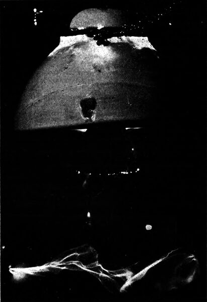
In Fig. 6 is seen a large triple petticoat potential insulator as it is breaking down under a maximum potential of about 130,000 volts. In this test one wire was connected to the wooden insulator pin, which was moistened, and the other to the top of the insulator. The other reproduction shows a 13-inch discharge. · · *Written for the Journal of the Worcester Polytechnic Institute.
|