[Trade Journal]
Publication: Scientific American
New York, NY, United States
vol. 21, no. 5, p. 68, col. 2-3
A NEW TELEGRAPHIC INSULATOR.
It has long been settled that insulation does not depend upon the mass of the non-conducting material as much as upon extent of surface, and the protection of the surface from deposition of moisture, or any substance calculated to decrease its insulating power. That insulator will therefore prove the most efficient that takes most fully into account these acknowledged facts.
 |
| Fig. 1 |
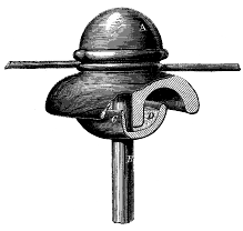
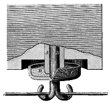
The invention herein described and illustrated, has for its object the attainment of such an insulator, by simple means, and to produce not only as near as may be a perfect insulator, but cheap and durable one. There are two classes of insulators in common use. The first is supported on a standard or peg, Fig. 1, and the second, Fig. 2, often called the hook insulator supports the wire by means of a hook, the shanks of which is screwed or otherwise fastened. into the insulator proper which in its turn is fastened into a wooden block of iron casing or some substitute therefore.
In the description of this insulator, we shall letter corresponding parts in both forms of the insulator similarly and describe them together. A is the insulator proper, made of glass, hard rubber or other suitable material; a section of the hook insulator and a sectional elevation of the other variety being presented.
 |
| Fig. 2 |
To these insulators the wire is attached in the ordinary manner. B is, in Fig. 1, the peg or standard supporting the insulator proper, A, and in Fig. 2, the shank of the hook screwed into the insulator proper, A; these supports being preferably made of malleable iron. Each of these supports has cast upon it or otherwise attached a cup, C. The insulator, A, is screwed down on the standard, B, Fig. 1, or the shank, B, Fig. 2, SO that it either touches, or nearly touches the bottom of the cup, C. The top of the cup, C, is shielded by the peculiar form of the insulator proper, A, Fig. 1, or by a recess cut in the under side of the block which sustains it Fig 2. The cup, C, extends out towards, but does not touch with its upper edge, either the insulator proper, A in Fig. 1, or the exterior of the recess cut in the supporting block, Fig. 2. Into the cup, C, is poured either melted paraffine, D, or any other insulating substance, paraffine being preferred as being both well suited to the purpose and cheap.
Thus a large extent of insulating surface is obtained between the line and the metallic supports, while at the same time the surface of the paraffine contained in the cups is protected from deleterious atmospheric influences.
This insulator has claimed for it the following advantages over those hitherto employing paraffine, as well as those not employing this insulating material:
First a greater surface of paraffine can be presented, thereby securing more perfect insulation.
Second, the dispensing with outside iron caps which invite lightning discharges.
Third, the placing of the paraffine in a cup right side up instead of bottom side up, and thus preventing all danger of the running out of the paraffine when melted by the heat of the sun, in hot weather.
Fourth, greater protection from atmospheric influences.
Fifth, general applicability to all common insulators.
Sixth, this insulator does not sensibly increase the cost over the ordinary insulator.
Should experience prove that these advantages are obtained as claimed, at no expense of other valuable principles such as strength, durability, etc., this improvement will be one of great scientific interest and practical value.
This invention was patented June 29, 1869, by W. E. Simonds, whom address for further information, at 845 Main st., Hartford, Conn.
