Tonawanda Power Company lines
|
[Trade Journal] Publication: American Electrician New York, NY, United States |
|||||||||||||||||||||||||||||||||||||||||||||||||||||||||||
|
THE WORK OF THE TONAWANDA POWER COMPANY. Transforming Niagara Power for Motors, Converting it for Railway Use, and Regenerating it for Arc and Incandescent Lighting. At Tonawanda, 10 miles from Buffalo and 14 miles from Niagara Falls, the transmission line from the falls to Buffalo is tapped and power from it is transformed, converted and regenerated into the various kinds and voltages of current desired tor traction, arc and incandescent lighting and distribution to motors. There is no electrical generating plant driven by steam power in Tonawanda or North Tonawanda either for street railway or central station loads. The work at Tonawanda is carried on by the Tonawanda Power Company, which is closely allied financially with the other Niagara power interests, such as the Niagara Palls Power Company and the Cataract Power and Conduit Company. The Tonawanda Power Company consists of the consolidation of the Tonawanda Light and Power Company, which formerly operated a steam-driven central station of the usual type in Tonawanda, and the Tonawanda Cataract Power Company, which previous to the consolidation was formed for advancing the Niagara power interests in Tonawanda. The consolidated company has erected a transforming station immediatey beside the right of way of the transmission line at a convenient point in North Tonawanda about a mile east of the business center and just a short distance south of the branch of the Erie running to Lockport, which branch is operated by electric power from this transforming station.
The general scope of the Tonawanda Power Company's operations is similar to that of the Cataract Power and Conduit Company of Buffalo as outlined in the January issue of the American Electrician. That is, the company transforms power as received from the high-tension transmission line to a lower voltage and distributes it to consumers desiring 25-cycle alternating current. The Tonawanda Power Company, however, goes further and converts power into direct current, which it delivers to the International Traction Company tor its street and interurban railways in the neighborhood, and also regenerates power by means of motor generators into forms suitable for arc and incandescent lighting, which it distributes and delivers just as does any central station corporation.
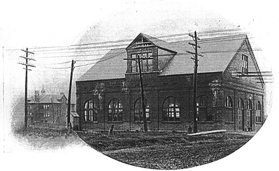
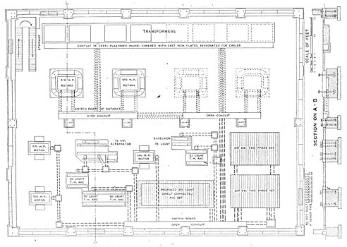
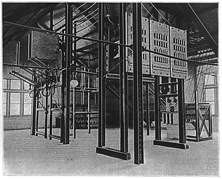
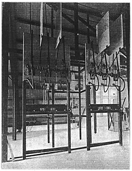
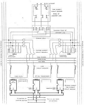
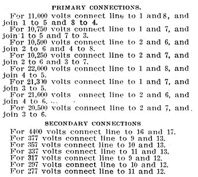
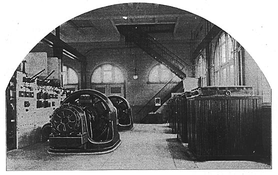
The transforming station, the exterior of which is illustrated in Fig. 1, is a brick structure about 60 feet square, with architectural pretensions somewhat above those of the average central station, as the picture shows. The main floor is divided by a row of steel columns into two bays, one of which, see Fig. 9, is occupied by the transformers for all purposes and the rotary converters for traction purposes. The other bay, see Fig. 10, is intended to contain the motor generators for supplying the arc and incandescent lighting circuits. The arrangement of the machines is shown in the floor plan, Fig. 2. The construction is fireproof, the floor being of concrete with a cement finish, with ample provision for the wire runs in the form of iron-covered subways and cross-connecting McRoy ducts and six-inch sewer pipes between these subways and the pits under the machines. The main operating room is not carried up into the roof frames, but is ceiled over above the cranes, which serve the two bays, giving a second floor. This upper story, which is a sort of attic occupying the four gables of the roof, see Figs. 3 and 5, contains the high-tension switchboards, circuit breakers, lightning arresters, and other apparatus which is cut into or connected with the high-tension lines before they reach the step-down transformers on the floor below. This station is somewhat of a new proposition in high-tension work, being a way station tapped into a transmission line and the junction point of a branch transmission line, viz., that running to Lockport. The general arrangement of the circuits is interesting on this account and also on account of the fact that they contain the first equipment of the Westinghouse Company's apparatus for reverse-current and time-element current-breaker protection, the General Electric Company's apparatus for which was outlined in the description of the Niagara-Buffalo transmission line recently described in these columns. The station taps both of the three-phase lines running past it from Niagara Falls to Buffalo, these two taps running in through reverse-current circuit-breakers to the high-tension bus bars of the station, indicated in the accompany diagram of the circuits, Fig. 7. By closing one set of these reverse-current breakers the station can be operated from line No. 1, and by closing the other set can be operated from line No. 2, or by closing both sets the station will get its power over both lines in parallel. The reverse-current feature is for use in the last case when a short circuit on one line would interfere with service on both unless the line affected was cut oft instantly by a breaker designed to open it in case the power flows in the wrong direction.* As soon as they enter the structure the two incoming branches from the two main lines outside the building are both tapped oft to a switchboard panel by means of which either one or both of them can be connected to the Lockport line. This arrangement is also shown in the diagram of connections. Fig. 7. The panel is termed a transfer panel, since by means of the switches upon it the Lockport branch can be transferred from one of the Niagara-Buffalo transmission lines to the other. Prom the transfer panel the Lockport circuit runs to a switch and time-element circuit breaker panel of General Electric manufacture similar to those previously described in these columns. From this panel the Lockport circuit runs out to the Erie tracks, along which it is carried on the poles, which also support the trolley wires.
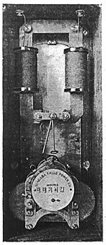
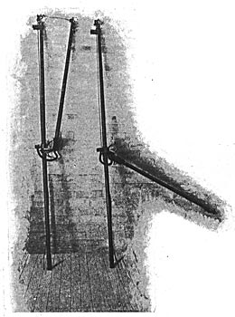
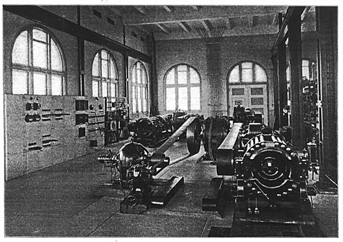
The transmission line from Tonawanda to Lockport, as well as the sub-station at that point, belong to the International Traction Company, to which power is sold in the 11,000-volt three-phase form at the Tonawanda station. The power is not measured on either an integrating or recording meter, but quite a novel form of instruments has been designed by Mr. P. M. Lincoln for measuring directly the factor of the load curves on which the charges are based. This factor is the aggregate length of time per month during which the load drawn is greater than that contracted for. The instrument, which is illustrated in Fig. 4, might be termed an overload-time meter, or a time-overload meter. It consists of a recording train measuring hours, driven by clock-work, the motion of which is stopped whenever the load is less than the normal amount which the circuit is supposed to take, and is allowed to operate only when there is an overload upon the line. The arrangement of the parts is obvious from a glance at the illustration. Above the clock-work and recording train is an alternating-current magnet with a laminated iron core, the coils of which are in the circuit of one of the series transformers operating the time-element relay of the circuit-breaker panel. Whenever an overload comes upon the line this magnet in the time-overload meter rotates its pivoted armature to such a position that the balance wheel of the clock is free to operate. Whenever the overload is removed the armature rotates back by gravity, catching the escapement of the clock and preventing it from runmng. The meter thus gives, every time it is read, a record of the number of hours that the line has been overloaded since the last previous reading. Similar meters are in use at other points in the Niagara system; for instance, on the total output bus bar of the 500-volt railway system downstairs in the Tonawanda sub-station. In this meter the magnet consists simply of a loop of iron surrounding the bus bar. This meter measures the overload of direct-current power delivered by the Tonawanda Power Company to the International Traction Company at Tonawanda. Referring again to the branches from the Niagara-Buffalo line as indicated in Fig. 7, it will be seen that these run through the choke colls of lightning arresters on their way toward the station circuits. The branches to the Lockport transfer panel are tapped off outside these choke coils so that the station apparatus is protected against any lightning entering over the Lockport branch by the same arresters that take off all lightning coming in from the Falls-Buffalo lines. These arresters are of the Wurts non-arcing metal type, grouped in the usual series-multiple way for high-tension circuits. They appear in the central foreground of the illustration of the upper room of the station. Fig. 3, the lower ends of the panels showing the graphite rod resistances which are cut in between the arresters and ground to prevent the high voltage and high power of these lines from holding an arc across even the many series non-arcing breaks of Wurts arresters. These resistances are such as to limit the dynamo current to five amperes.
From the lightning arresters the two taps run respectively through the two sets of reverse-current circuit breakers, from which they run together in common high-tension bus bars which are tapped off through other protective apparatus to the high-tension sides of the step-down transformers. The reverse-current circuit-breakers are made by the Westinghouse Company and differ materially both in construction and in principle of operation from the General Electric reverse-current breakers described previously in these columns. The breakers themselves, which appear in the foreground of Fig. 3, are of the Westinghouse Company's familiar stick type with the long arms and deep barriers necessary for high-tension work, the Westinghouse engineers believing in breaking the arc by sheer length of opening in air rather than shunting the breaker with a fuse, as is done by the General Electric engineers.
The relay system of these reverse-current breakers is much more elaborate than that of the General Electric Company's reverse-current breakers described in the January issue of this paper, being designed to respond to a greater variety of conditions of safety and danger of the circuits. The reverse-current relays themselves in this case are small induction motors of the form used by the Westinghouse Company in its induction wattmeters. The two windings of each of these induction motors are connected respectively with potential and current transformers very much as are the two windings of the direct-current tan motors used for the same purpose by the General Electric Company. The rotatable part of the relay motor instead of driving a recording train turns a crank carrying a movable contact which normally rests against a dead back stop, while, if the torque reverses into the other direction, the contact comes against the live front stop, which closes a local circuit, which in turn trips the breakers. The connections between the series transformers and the relays are quite complex. In the first place, there, is only one relay for all three phases of each line to be protected, this relay being a double induction motor with two motors mounted on one vertical shaft just like the double induction motors used by the Westinghouse Company for polyphase meters. The two relays, one for each of the two three-phase lines to be protected, have their circuits interconnected through potential, current and auxiliary transformers much too elaborate and technical for description in these columns. The arrangement is such that if power tends to flow outwardly from the junction point toward line No. 1 the relay of line No. 1 operates, throwing the breakers of line No. 1, but relay No. 2 only holds the firmer against its back stop. On the contrary, if power comes in through line No. 1 and goes out again through line No. 2, relay No. 2 operates, relay No. 1 remaining in its normal position. It will be noticed that in this case there are three circuit-breakers per line, one in each leg of the circuit, although there are only two series transformers. The tripping colls of all three circuit-breakers of one line are wired in parallel to the corresponding relay so that all three are opened simultaneously.
Taking up the main high-tension circuits again, they run from the high-tension bus bars to the transformers in the station through a novel type of safety device which has been termed a fuse circuit-breaker. Two of these odd devices are shown in Fig. 6, one open and one closed. Each consists fundamentally of an aluminum wire about one foot in length, fastened in carbon clamps and stretched between the upper ends of two long wooden poles. At its lower end the shorter ot these poles is hinged to the other and forced by a spring so as to keep the aluminum wire stiffly stretched. The current is led through the aluminum wire, which is designed to fuse at 50 amperes. In case it does melt, the pole is forced outwardly by the spring and is rotated about its pivoted lower end by gravity, giving an opening of about six feet. Current enters and leaves the whole device through jaws which render it removable from the knife contacts on the marble panel on which it is mounted. By grasping the extended lower end of the longer pole the fuse breaker can thus be readily removed for re-fusing. A string is attached to one of the carbon clamps around the aluminum wire, so that the clamp can be opened at any time while the device is in circuit, thus freeing the spring-actuated arm and opening the line. It will be noticed from the diagram that there are six of these fuse breakers and that they are not connected directly in the legs leading from the high-tension bus bars to the corners of the delta formed by the primary windings, but are connected within this delta, two in each phase; thus each primary winding has in series with it two fuse breakers, one at each end. By this means the blowing of any one of these fuse breakers only throws one of the step-down transformers instead of two, as would be the case were the breakers connected in the usual way into the three legs of the circuit running to the delta. As is well known, when one of three delta-connected transformers is opened, the other two will continue to deliver tnree-phase currents, while, if two are opened, only one phase remains in service.
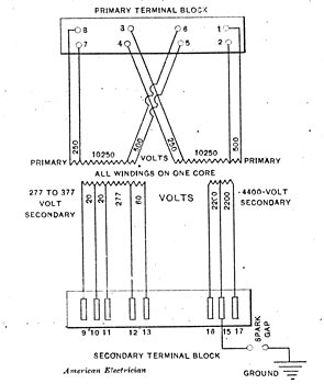
From these fuse circuit-breakers the line runs downstairs to the step-down transformers. These transformers, which appear to the right in Fig. 9, are of the Westinghouse make and of the oil-insulated self-cooling type. They are four in number, three of them being delta-connected on both primary and secondary sides, the fourth being a spare. There is room provided for four more. Each is rated at 500 kw. The distinguishing peculiarity of these transformers is that each has two entirely independent secondaries, one wound for 4400 volts and the other tor 360. These two secondaries are designed to supply simultaneously the two different classes of service to be carried from this station. The higher voltage is intended tor the distribution of 25-cycle power to outside consumers, the rather high pressure (for urban distribution) of 4400 volts being adopted on account of the location of the station somewhat out of the center of distribution. The lower pressure of 360 volts is designed tor supplying the railway rotaries and the motors of the central station motor generator sets. The combination of tne two entirely distinct secondaries tor separate purposes in one group of transformers is quite a novelty in alternating-current work, but introduces several advantages in cases of this kind. In the first place, it reduces the number of transformers necessary and proportionately increases the rated output of each (thereby reducing the nrst cost per kilowatt and increasing the efficiency, and in the second place it allows one service to be considerably overloaded it the other is underloaded, as the currents through the primary are the resultant of both loads, and the cool running of one secondary allows the other to run hot without overheating the whole transformer. The two secondaries of each transformer are designed for loads of 250 kw. each when both are loaded. When one is on open curcuit the other is allowed to carry 300 kw. These transformers are provided with an unusual number of taps from the windings to provide tor many different voltages. Fig. 8 shows a diagram of the terminals of primary and secondary windings, and the table immediately below it gives the voltages obtained by connecting into different terminals. This table gives the voltages which would be obtained from the different connections, assuming the same density of magnetization of the transformer iron in all cases.
There are two primary windings which are now connected in parallel, but which may be connected in series with each other when the line voltage is doubled. By means of taps into both ends of each of these windings, one tap cutting off from one end twice as many turns as does the other tap from the other end, the transformer may be suitably connected to obtain its normal density from a line pressure of 11,000, 10,750, 10,500 or 10,250 volts, as the table indicates. By connecting the two primaries in series with each other, voltages just twice all of those above mentioned may be provided for. The low-voltage secondary has provision for regulation by 20 volt steps all the way from 377 volts down to the remarkably low figure for rotary converter purposes of 277 volts. This is provided to allow tor a considerable rise of primary voltage above even the maximum figures with normal density on the transformer. As 11,000 volts is delivered in Buffalo the pressure rises at Tonawanda at times considerably above this, so that even with all primary turns in circuit the secondary voltage delivered is considerably higher than that given by the table, enough so to bring the voltage across the smallest number of secondary turns between terminals 11 and 12 up above 300 volts, or into the proper range tor the three-phase end of the railway rotaries. The transformers are easily able to withstand any increase of voltage which they are likely to have. The spark gap, which is indicated in the same diagram as connected between the middle of the secondary winding and ground, is provided to prevent straining the insulation of the 4400-volt secondary in case of leakage of current from the 11,000 or 22,000-volt primary. The gap is so set that current will jump across when the pressure rises to a value somewhat higher than 4400 volts. It this excessive potential is momentary the gap will simply spark and instantly cease. It however, the potential is maintained, the sparking will continue, the two cylinders of the gap will be welded together and the secondary will be permanently grounded. Of the three transformers forming the delta, the gap is connected to the secondary of one only. A similar spark gap is not used on the 360-volt secondary since this is already grounded through the winding of the rotary converter and its negative brush, which is connected to the railway tracks. Another peculiarity of these transformers is that their secondaries are only connected in delta through the switches on the switchboard, there being three double-pole switches instead of three single-pole or one triple-pole, to throw them into the bus bars. This arrangement, which is indicated in the main diagram, Fig. 7, allows the three circuit-breakers in the low-tension sides to be included within the delta instead of cut into the three legs running from the corners of the delta to the load. This unique arrangement of the secondary circuit-breakers is provided so that in case there comes a short circuit in one transformer, the fuse breakers in the primary and the reverse-current breakers in the secondaries of this one phase will open allowing the other two transformers to continue working, delivering three-phase currents. In case the breakers were cut into the legs of the circuit outside of the delta, the opening of one breaker would throw out two transformers, leaving only one at work, delivering only one phase. This would throw a very heavy load upon the one phase remaining at work, while, it two transformers remain in circuit supply motors or rotaries, the apparatus continues working practically as well as with three.
The secondary circuit breakers are of the usual overload type, with time-element attachment, and also have auxiliary tripping coils of the reverse-current relay time-element type, using induction meter motors for relays, but in this case each of the three phases has its own separate single-motor relay. These relays are shown mounted on a panel in Fig. 5. Immediately below each one is a four-part plug and six-part receptacle by means of which the potential element of the relay motor can be reversed to test the operation of the device. Another peculiarity of these relays and their circuits is the fact that each relay is connected'with series transformers of the same phase in both the 4400 and the 360-volt secondaries, and in case either reverses, the relay operates, throwing the breaker of the corresponding phase in both outputs. A sort of time element is introduced into these relays by putting on the rotating disc a magnetic brake like that used in the meters. This, however, does not give a time lag independent of the overload, since the greater the overload the stronger is the force acting against the magnetic drag. In both secondaries the Indicating ammeters upon the switchboard are also connected within the deltas, so that each one reads the load upon each phase. The total apparent power is then the sum of the ammeter readings times the voltage, and there is no necessity of a calculation introducing the square root of three to find the power from the ammeter readings. The 4400-volt output is arranged with induction regulators for varying the voltage.
The rotary converters are two in number, rated at 500 h. p. each, both working on the interurban and Tonawanda loads of the International Traction Company. These rotaries are of the Westinghouse construction, as the view of the small induction starting motors in Fig. 9 clearly shows. They are fitted with magnetic oscillators similar to those used in the past on General Electric rotaries and, like them, intended to oscillate the shafts axially and prevent the brushes from wearing tracks or grooves into the commutators and collector rings. The oscillators on these machines are located within the overhanging rotors of the starting motors. The rotaries are compound wound and fitted with an equalizer. They supply the trolley lines over four 600,000 c. m. uninsulated copper cables. All the 500-volt copper is tied together between the Buffalo city line and Lockport and Niagara Falls, thus throwing the rotaries at Tonawanda in parallel with those both at the Falls and Lockport. The circuit-breakers on the direct-current ends of the rotaries are fitted with auxiliary tripping devices intended to open them it the breakers open on the alternating-current end. In case the a. c. power is cut off, the rotaries continue to run as d. c. motors, taking current from the other stations. This current comes through the series field coils in the reverse direction from normal, weakening the fields, speeding up the machines, causing more current to flow in to keep them running, and finally causing them to run away.
The other bay of the lighting station is at present occupied by three 100-h. p. Westinghouse type C induction motors belted to arc and 125-cycle 1100-volt single-phase alternators. The alternating system is, however, to be changed over to 2200-volt 60-cycle two-phase and carried at night by two 200-kw. direct-coupled motor-generator sets, the motors to be of the induction type. The motors will have eight poles and the generators twenty, giving a ratio of frequency of 8 to 20, or 25 cycles to 62 1/2 cycles when there is no slip. The slip of the motor under load will, however, bring the frequency down to about 60 cycles on the generator end, These two-phase 60-cycle generators will take care of the small motor load, so that it will be necessary to run the 4400-volt 25-cycle circuits only to the larger consumers having motors over five h. p. The present capacity of the lighting system is 275 arc lamps and 2000 incandescents. A 60-k-w. belted set will be installed for the day load. A pair o£ 125-light Brush arc machines will also be installed at some later date, when the load demands them, direct coupled to one motor tor carrying the arc load. The credit for the original worn involved in the design of this novel station belongs to Mr. L. B. Stillwell, Electrical Director of the Niagara Falls Power Company and associated interests, and to the engineering staff of the Westinghouse Electric and Manufacturing Company. The officers of the Tonawanda Power Company, to whom thanks are due for the information given above, are Mr. A. S. Allen, Superintendent, and Mr. W. R. Gibboney, Electrician. An explanation of many of the unusual alternating-current devices was obtained from Mr. L. E. Imlay resident engineer of the Westinghouse Company at Niagara Falls, in whose charge was placed the erection of the apparatus in this station. *The general scheme of this protection was fully explained in the article on the Falls-Buffalo Transmission line in the January issue of the American Electrician.
|