Various forms of insulators for telephone work
|
[Trade Journal] Publication: The Practical Telephone Handbook London, England |
||||||||||||||||
|
Insulators.—As the wire used for telephone lines is generally bare and must be supported at frequent intervals, it is necessary to provide special insulators, to which the wire may be attached, and so prevent excessive leakage through the poles, which are not sufficiently good insulators in themselves. In addition to having high insulating qualities, the insulators must have sufficient strength to resist the heavy stresses to which they are subjected. Material.—This has varied from the original goose-quill to earthenware, glass, ebonite, and porcelain. White porcelain has given the best results ; but well-glazed earthenware follows it closely, and has the merit of being cheaper. The principal requirement is that the material must not be porous, and must have a fine glazed surface which is not hygroscopic—that is, has a surface on which moisture will not readily condense. Experience has shown that leakage does not take place through the body of the insulator, but is altogether a matter of surface conduction by means of the films of dirt or moisture deposited on it. Form.—In designing the form, the object has been to make the surface over which the leakage must take place as long and narrow as possible consistent with strength, as the law of resistance is the same for films of moisture, etc., as for other substances. A dry portion of such surface must also be preserved in the wettest weather, which object is attained by making the insulator in the form of an inverted cup or cups.
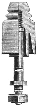
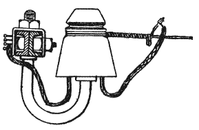
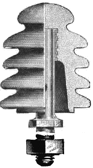
Cordeaux's Screw Insulator.—This is probably the one which answers the above, and certain other requirements to the fullest extent, for which reason it is mostly used for important telephone lines. Fig. 325 shows one form of it partly in section, and the galvanised iron bolt used in conjunction with it. It is a double-shed form of insulator, which means that it is in the form of an inverted double cup. Single-shed insulators have only one inverted cup. It will be seen that a great length of surface is opposed to the leakage between the wire (which is fastened in one of the grooves) and the bolt. The screw arrangement shown allows of the insulator being taken apart from the bolt, when in position, for the purpose of cleaning out the inside, or to change the position of the wires on the poles. An india-rubber ring, put over the screw, is sometimes used to allow for the difference in expansion by heat between the iron and the porcelain. The form of Cordeaux insulator used by the British Post Office is rather larger, and has only one groove. The S.I. Insulator.—Fig. 325 shows the form of Cordeaux insulator used by the National Telephone Co. for all ordinary purposes. The straight bolt shown in connection with the Cordeaux insulator, Fig. 325, is only suitable for straight, or nearly straight, through work. For terminating—that is, when the wires are cut at the insulator, or where the wires go off at an angle— some form of what is known as the J bolt, Fig. 326, is used. As will be seen, the line of the wires is brought nearly opposite the centre of the arm, so that there is no turning stress in a vertical direction. The plane of the bolt also takes the direction of the resultant pull. The J bolt has also another advantage, as it acts as a flexible spring to the wires, giving way a little under excessive stress, due to extreme cold, snow, etc., and thus relieving the wires from excessive strain.
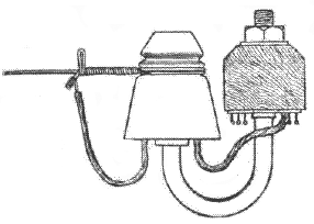
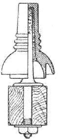
The last figure shows the J bolt attached to an iron arm, and Fig. 327 shows it adapted to a wooden arm. Both these figures also show attachments to the arms, recently adopted, for carrying the leads in a tidy manner. "Double J" bolts are also often used on the ends of arms for accommodating two wires going off at an angle. The Langdon Insulator, Fig. 328, is sometimes used for terminating wires which cross railways, etc. It has three grooves, a long and strong bolt with a broad flange, and the grooves are low down. It is not so good as the J bolt and S.I. insulator for strength.
The Bennett Insulator (Fig. 329).—This is a single-shed insulator, and was specially designed by Mr. A. E. Bennett to meet the various demands of telephone work. It has been extensively used. It has four grooves, in the two topmost of which wires may be terminated, and if the wire is a light one both terminations may be made in the top groove. The Bennett insulator is especially strong in resisting damage by stone - throwing, usually a costly item in maintenance.
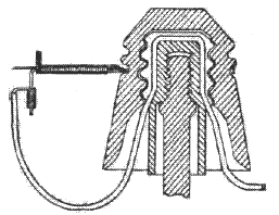
The S.A. Insulator. —This is a special form, invented by Messrs Sinclair & Aitken, and used where a line terminates and a covered leading-in wire is to be attached to connect to an instrument, or otherwise. As seen in Figs 330 and 331, it is made in two parts, which screw together. The inner cup has a deep recess cut through screw and top large enough to accommodate the leading - in wire, so that when the outer cup is screwed on, the wire is well protected from the wet, surface leakage along the outside of the covered wire being thus prevented by a dry portion being preserved in the cup. The joint or "nib" should be turned horizontally for easy soldering, and not vertically, as shown in the figure.
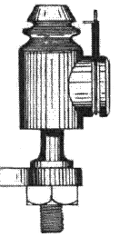
Spur Insulator.—This is an insulator of the form shown in Fig. 332, fitted with a grooved boss on the outer shed, so that it enables vertical or nearly vertical wires to be readily attached. It should be double-shed, and should not be used for leading-in terminating at sub - stations unless it is provided with a screening arrangement for the covered lead similar to the S.A. insulator. Some S.A. insulators have lately been fitted with "spur knobs" for the purpose of terminating vertical wires.
|
