[Trade Journal]
Publication: American Electrician
New York, NY, United States
vol. 14, no. 8, p. 371-381, col. 1-3,1-2
RECONSTRUCTED CENTRAL STATION AND SUB-STATIONS.
PLANT OF THE NEW YORK & QUEENS
ELECTRIC LIGHT & POWER COMPANY.
A short time ago the properties of the Electric Illuminating and Power Company, of Long Island City., L. I., the New York and Queens Gas and Electric Company, of Flushing, L. I., and the Jamaica Electric Light Company, of Jamaica, L. I., were consolidated under the name of the New York & Queens Electric Light & Power Company. The power house of the Electric Illuminating & Power Company was located on the East River at Astoria, L. I., and before the consolidation it contained one 500-kw., one 300-kw., and one 75-kw. alternating-current generators, the first two being Westinghouse two-phase 60-cycle machines with armature shafts direct-coupled to vertical compound Williams engines running at 150 r. p. m. The 75-kw. generator was a belt-driven General Electric machine. The station also contained eight 50-light T.-H. and two 50-light Brush arc dynamos, which were driven through a jack-shaft by two slow-speed horizontal Corliss-type engines.
| |||
| Bob-Caption |
The plant of the New York & Queens Gas & Electric Company was located on Flushing Creek, in Flushing, and was equipped with a 120-kw. two-phase generator belted to a Westinghouse three-cylinder gas engine, three 75-kw. two-phase 60-cycle alternators, three 75-light, one 90-light, and two 150-light Westinghouse arc machines belted direct to Westinghouse compound engines. Illuminating gas from the street mains was used in the gas engine, and the generator driven by it was operated in parallel with the three small alternators during the peak of the load.
The power house of the Jamaica Electric Light Company was situated at Dunton, a short distance outside of Jamaica, on the line of the Long Island Railroad, and contained twelve Ball arc machines ranging in capacity from 70 lights to 160 lights, belted to six Ames simple engines, one 150-kw. and one 50-kw. Stanley two-phase 133-cycle generators, belt-driven, for incandescent lighting and power purposes.
 |
| Bob-Caption |
The Astoria plant was of modern design and the building a substantial brick and steel structure, the engine room being 80 x 90 1/2 feet and the boiler room 70 x 75 2/2 feet. The Flushing and Jamaica plants were of inferior design and construction, and were being operated very uneconomically. The plans for reconstruction involved the abandonment of the steam generating stations at Flushing and Jamaica, and provided for the enlargement of the power plant at Astoria, and for the transmission of power for arc lights, incandescent lights and motors from this end to sub-stations in Flushing and Jamaica. The two small plants have therefore been replaced by sub-stations of modern design and construction. The old-style direct-current. arc lamps used in Long Island City and Jamaica have been replaced by modern series alternating-current enclosed arc lamps, and the incandescent lighting and power systems of Jamaica changed from 133 cycles to 60 cycles, thus making all three systems uniform and of modern type.
Current is generated and distributed at Long Island City at 2200 volts, two-phase, and it is transformed by the Scott method to 7500 volts, three-phase, for transmission to the two sub-stations, where it is used at this pressure by General Electric constant-current transformers. For incandescent lighting and power purposes it is transformed back to 2200 volts, two-phase. Constant-current transformers in the main station are supplied at 2200 volts from the bus-bars, and raise this voltage to that necessary to operate 75 and 100 arc lamps in series.
The transmission e. m. f. of 6600 volts, with a maximum of 7500 volts on full load, was chosen because it was believed that much less difficulty would be experienced in gaining permission to operate at that voltage with inconspicuous glass insulators than if the line were operated at a higher potential with large white porcelain insulators. Moreover, since it was necessary to use a fairly large size of wire in order to obtain sufficient mechanical strength, and since the distance of transmission was comparatively short, the saving by operating at 10,000 volts would not have been as great as it might seem at first glance.
| |||
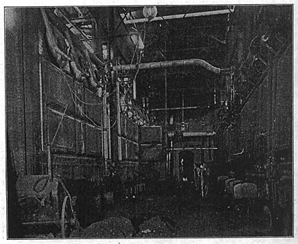
| Fig. 4. View in Boiler Room. |

The generating station is admirably situated to obtain its supply of coal and condensing water at the lowest cost, and is located almost equidistant from the two sub-stations. The building was originally designed for several units of somewhat smaller capacity than those that have been installed, so that the reconstruction has only necessitated some slight changes in the structure to accommodate the new apparatus. The work of reconstruction, however, was difficult since it was necessary to make all the changes in the steam and electrical apparatus without interfering with the regular operation of the plant.
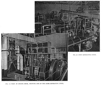
The two Corliss engines and jack-shafting of the original station have been replaced by three vertical cross-compound condensing engines, built by the Fulton Iron Works of St. Louis, Mo., and direct-connected to 750-kw. Stanley alternators. The engines, which are shown by Fig. 2, are of the side-crank type, with the flywheel and generator mounted on the shaft between the frames. Each engine delivers to the generator 860 horse-power at its most economical load with a steam pressure of 140 pounds and 26 inches of vacuum, when running at 113 r. p. m., and is capable of developing 1200 indicated horse-power continuously, and a maximum of 1375 horse-power for a short period.
| |||
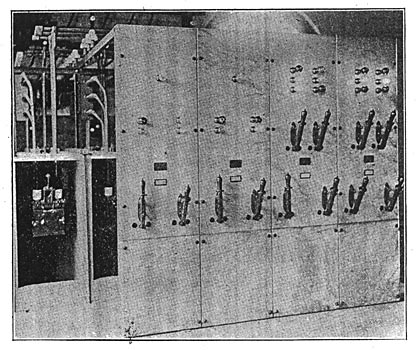
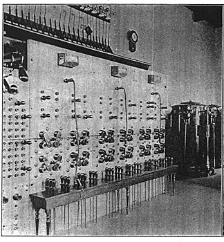
| Fig. 5. Main Switchboard at Astoria. |
The engines and governors are so designed that when running at the same speed under any load between friction load and one-fourth overload, the amount of work done by each of the engines is practical equal to the amount of work done by each other engine in operation, and the maximum change in speed due to any instantaneous change in load of 225 indicated horse-power between friction load and one-fourth overload does not exceed 3 per cent. The governors permit the speed of each engine to be reduced from its rated speed of 113 r. p. m. to 5 per cent below, or increased to 5 per cent above while in operation.
The frame and bases and the general design of the engines are similar to the well-known Reynolds-Corliss vertical type. The cranks are in quadrature and are overhung. The main bearings are of the water-cooled removable-shell type. The cylinders are not steam jacketed, but their walls are sufficiently thick to provide for reboring twice or increasing their internal diameter three-fourths of an inch without rendering them unsafe or unfitted to perform the service required. The cylinders are 21 inches and 42 inches in diameter, respectively, with a stroke of 42 inches. The valve-gear is of the double-eccentric releasing Corliss type with the valves in the cylinder heads to reduce the clearance. The receivers are of the cylindrical re-heating type, supported by means of brackets on the high and low-pressure frames. The reheating surface is composed of two-inch straight tubes expanded into bored tube seats, the heads being placed in the center section of the receiver. The exhaust from the high-pressure cylinder enters the receiver and passes through the inside of the re-heating tubes to the low-pressure cylinder, live steam surrounding the outside surface of the re-heating tubes. The engines are provided with two galleries, the upper ones being connected together so that the operators may pass directly from one unit to another.
Steam is supplied by four Caldwell horizontal water-tube boilers and three Altman & Taylor water-tube boilers, having a total nominal rating of 2900 horse-power. The boilers are set in batteries of two, and are hand-stoked with a mixture of washed culm and bituminous coal. Draft is furnished by a single brick stack 190 feet high and 9 1/2 feet inside diameter, located in one corner of the boiler house. The feed-water pumps are located in the pump house built for the purpose, adjoining the boiler room. This room contains an 8 x 12 x 6 x 12 compound duplex outside-packed, plunger-type pump, built by the George F. Blake Manufacturing Company, and two 6 x 9 x 5 1/4 x 10 Worthington compound duplex pumps of the piston type. The room also contains two 1500-h.p. Goubert feed-water heaters, which utilize the exhaust steam from the auxiliaries for heating the feed-water.
 |
| Bob-Caption |
Each of the new engines is equipped with an independent condenser set composed of a Wheeler "Admiralty" surface condenser and a steam-driven Blake vertical twin-beam air pump. The condenser is of the rectangular pattern with a cast-iron shell. The tube-heads are of bronze and the tubes are of seamless drawn brass tinned inside and out, and held in place in the tube-heads by screw glands in order to provide for expansion and contraction. The air cylinders are provided with solid bronze buckets and rods, and contain three valve decks. The steam cylinders are supported in a line directly over the air cylinders by a cast-iron entablature, to which they are bolted; also by steel columns from the tops of the air cylinders. The valve-gear is of the well-known simplex type, capable of adjustment for length of stroke while the pump is running. It is proposed to use the water of condensation for boiler feed, together with such additional supply from the city mains as may be required to make up the usual losses. The condenser for the two old units is also of Wheeler manufacture and is placed between the engines.
 |
| Bob-Caption |
The circulating pumps are situated in the basement, and the engine-room floor is left open above them. The plant is equipped with two Blake horizontal tandem-compound circulating pumps, each having a high-pressure steam cylinder of 14 inches, a low-pressure cylinder of 20 inches, and a water cylinder of 30 inches diameter, the stroke of all being 24 inches. These pumps are adapted for handling salt water; that is to say, they are provided with composition plates for both suction and discharge valves, which project through and beyond the flanges of the main casting. This is a feature .of these pumps, it being common to screw or drive brass seats into iron castings, and these sooner or later become loose, owing to the corroding influence of the salt water. The water cylinder of each pump has a special lining which extends from head to head, the ports being cut through the lining. The steam cylinders are in tandem in one casting,
 |
| Fig. 8. Views Showing Arrangement of Condenser and Connections. |
and the piston-rods are arranged so that there is no inconvenience in getting at either the high or the low-pressure pistons, or in packing the piston-rod stuffing boxes. The low-pressure piston has two rods which pass through sleeves cast on the sides of the high-pressure cylinder, thereby doing away with inside stuffing boxes. The stuffing boxes are on the ends of these sleeves on a line with the stuffing box of the piston of the high-pressure cylinder. By this arrangement the three stuffing boxes are outside of the lagging and thus very convenient for repacking. The two low-pressure rods and the high-pressure rod, as well as the pump rods, connect to a common cross-head. The valve-gear is of the simplex type. Heavy polished steel rods connect the steam and water ends. The pumps are run non-condensing, the exhaust passing through two 1,500-hp. Goubert feed-water heaters.
| |||
| Fig. 9. One of the Exciter Units. |
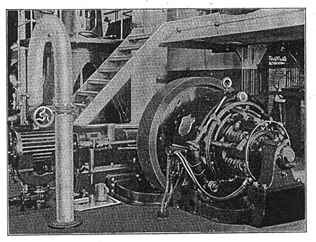
Fig. 2 is a plan view of the Astoria plant, showing the arrangement of the apparatus. It will be seen that provision for one more unit has been made. The new engines and generators are placed in a row along the division wall, and the old units-are situated in the two center bays opposite them; one of the remaining bays is occupied by two 50-kw. engine-driven, and one 40-kw. motor-driven, exciting units. The engine-driven exciter generators were furnished by the Bullock Electric Manufacturing Company, and the engines by the Harrisburg Foundry and Machine Works, Harrisburg, Pa.; the motor-driven set was furnished by the Westinghouse Company. One of the engine-driven exciters is shown by Fig. 9.
| |||
| Fig. 10. High-Tension Switchboard at Astoria. |
The boilers are placed in two rows at right angles to the line of the engines, the Caldwell boilers occupying one side of the boiler room and the Altman & Taylor boilers the other. This arrangement was fixed at the time of the original construction of the station. The flue is controlled by a Locke damper regulator, and is divided into two sections, each having an opening 7 1/2 x 7 1/2 feet, and the opening extends along the sides of the division wall of the building in the boiler-room basement.
 |
| Bob-Caption |
Steam from each boiler is conveyed by boiler bends to 14-inch steam headers, one for each line or boilers, and each boiler header is connected by means of long-radius bends to a 14-inch equalizing header, from which two branches are joined to each of the new engines. A sub-header is run from the main header for supplying steam to the old engines, and a branch from this forms an auxiliary steam header for feeding the auxiliaries. A duplicate connection is also made with the auxiliary header from the main header. Full-weight standard lap-welded pipe is used on all steam lines 1 1/2 inches and larger, and butt-welded standard-weight pipe is used on 1 1/4-inch steam lines and smaller. All pipe joints 5 inches and smaller are made up of extra-heavy cast-iron raised-seat screwed flanges. All pipe joints 6 inches and larger are made of extra-heavy gun iron with raised seat and screwed flanges. All fittings 2 1/2 inches to 5 inches, inclusive, are extra-heavy cast-iron flanged fittings. All fittings 6 inches and larger are extra-heavy gun- iron flanged fittings. All valves 2 1/2 inches and larger, are extra-heavy flange, out-side screw-yoke gate valves; valves which are 7 inches and larger being by-passed. All valves 2 inches and smaller are of the Crosby spring-seat screwed-end type. The gaskets for joints on the live steam lines are made of corrugated copper. The gun iron used in the flanges and fittings was tested for a tensile strength of 27,000 pounds per square inch. The exhaust and water piping is composed in general of standard cast-iron pipe with joints made up with Rainbow gaskets.
 |
| Fig. 12. Transmission Line Pole. |
The heavy steam drains from the headers and engine receivers are collected and returned to the boilers by the Holly gravity return system. Each independent drain is connected to a header that discharges into the Holly receiver, and is also by-passed into a low-pressure drain header, which discharges into the river, thus providing means for repairing the Holly header if required. The low-pressure drains from the exhaust piping, shells of engine receivers and blow-offs from cylinders are piped to the header which discharges into the river.
 |
| Fig. 13. Arrangement of High-Tension Switches. |
The feed and boiler blow-off lines are made of wrought-iron pipe with extra heavy fittings and gate valves, in accordance with the specifications for material for live-steam piping. The entire piping installation was furnished and erected by the Best Manufacturing Company, Pittsburg.
| |||
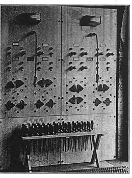
| Fig. 14. Arc Switchboard at Jamaica. |
| |||
| Fig. 15. Arc Board at Astoria. |
The plant is equipped with a gravity oiling system whereby oil is available under pressure to each oil cup of the engines, thus insuring good lubrication. The system consists of a large storage tank for receiving and storing oil drained from the filter and such additional new oil as is required. From this tank it is pumped by a small pump to a gravity tank located in the roof trusses of the boiler room. From this gravity tank a 2-inch supply is piped to the basement and runs by each new engine. From the supply pipe branches are piped to the oil cups of each engine. The oil, as it drains from the various journals of the engines, is collected in the crank pits, which are piped to a draining system which discharges into a 600-gallon Turner oil filter situated in the basement, where the oil is filtered and pumped again into the oil storage tank. The switchboards and transformers are located on a gallery extending along the front wall of the building. The generator board is placed on a wing leading from the main gallery and contains one motor and two engine-driven exciter panels, five generator panels, one station panel, one transformer feeder panel, one arc-light feeder panel, one local feeder panel, and two local distribution panels. Fig. 5 shows the board and Fig. 11 is a diagram of the connections. The diagram shows but one 750-kw. generator panel, but there are three of these, the wiring, of course, being identical. Each of the generator panels contains two indicating wattmeters and ammeters. The station panel has four single-phase recording watt-meters, and each of the feeder panels is equipped with two polyphase recording wattmeters; and a swinging bracket at the end of the board carries three voltmeters, two of which are connected to the two sets of bus-bars, and the third may be plugged on to either phase of any generator.
 |
| Bob-Caption |
The arc-light board, which is on a line with the main board and separated from it, is shown by Fig. 15. It contains two eight-circuit panels, each providing control for four arc-light regulators. The connections are so arranged that the board may be fed from the duplicate set of bus-bars, and any transformer may be connected to any set of bus-bars. Near the center of the main gallery is connected a two-panel switchboard for controlling the primary side of eight 200-kw. air-blast step-up transformers, which raise the voltage from 2200 to 7500 for transmission. The secondary pressure may be varied from 6600 volts to 7500 volts in four steps by changing the connections to the taps on the primary side. The air-blast apparatus has been installed in duplicate, and a spare transformer provided, so that no interruption to the circuits may be caused by failure of any part of the transforming apparatus. The secondaries of the transformer and transmission lines, which are in duplicate, are controlled by a four-panel switchboard located at one end of the main gallery.
The transformers are used in pairs for transforming 60-cycle two-phase currents to three-phase currents for transmission, and vice versa. The step-up transformers deliver, 200 kilowatts to the three-phase transmission line at a potential of 7500 volts between line wires, the primary side of the transformers being supplied with current at a potential of 2200 volts and the power factor being .80. The step-down transformers deliver 100 kilowatts to a two-phase circuit at a potential of 2100 volts when the primary is supplied with current at a potential of 6600 volts, the power factor being .80
| |||
| Bob-Caption |
The transformers are capable of operating continuously at full load for twenty-four hours without heating over 40° C. above the temperature of the surrounding air. They are also capable of carrying one-fourth overload for two hours without heating more than 50° C. above the temperature of the surrounding air and of taking a 50 per cent overload momentarily without injury. When supplying a load with a power factor of .80 the efficiencies of the transformers vary from 98 per cent at full load to 94 per cent at quarter-load. The drop in secondary voltage from no load to full load is less than 4 per cent. Means are provided for connecting the step-up transformers so that the transformed voltage may be made 6600, 6800, 7000, 7250 or 7500, by changing connections on the low-pressure side. The insulation resistance between the high-pressure windings and the core, as well as that between the high and low-pressure windings, is sufficient to withstand 15,000 volts from a source of alternating current having a capacity of 25 kilowatts. The low potential winding withstands a similar test with current at a potential of 5000 volts. Both of the windings have an insulation resistance between themselves and the core of one-half megohm. The transformers are designed to operate in multiple and to divide the load evenly. The two-phase induction regulators used to regulate the circuits leading from the step-down transformers are capable of raising or lowering the potential of these transformers 10 per cent. These regulators are operated by hand wheels.
General Electric oil switches are used throughout. Those for controlling the two-phase circuits are each two-pole double-throw, two of them being operated by one handle, thus forming virtually a four-pole double-throw switch. They are mounted one above-the other on the walls of the building back of the switchboard, and the operating handles are mounted on the front of the panels. The three-phase high-tension switches are placed in brick compartments and located in two rows back to back on the gallery behind the high-tension board, as shown by Fig. 13. The transformers are protected by fuses in the primary circuits, and the transmission lines are equipped with overload relays, which trip the high-tension switches if any overload or short-circuit occurs on the line. The bus-bars are in duplicate throughout, and a signal system has been installed at the main and sub-stations which prevents two sets of bus-bars from being paralleled at any point excepting at the main board.
The signaling is done by vari-colored incandescent lamps mounted over each switch on the high-tension board, and so connected that when a switch on the primary side of the transformers is operated the lamp indicates the proper secondary switch to be thrown. A signaling system is also provided on the high-tension transmission line. This consists of an incandescent lamp at each end of the line supplied through a small transformer and so connected as to light when the circuit is thrown on, thereby indicating to the switchboard attendant that the line is in working order and alive. Fig. 16 is a diagram of the high tension wiring.
The transmission line consists of two three-phase circuits. No. 0, insulated copper wire being used from the power house to a point two and one-half miles distant, where each circuit branches off to the sub-stations. The line to Jamaica extends 7 miles from the junction point, and the two circuits are made up of No. 3 insulated wire. The line to Flushing is three and three-quarter miles from the junction, and No. 4 wire is used, making a total of fifteen and three-quarter miles of transmission line. The lines are supported by 45-foot chestnut poles placed 100 feet apart along the highway. The wires are carried 18 inches apart on 4 1/2-inch triple-petticoat glass insulators and are supported in tri-angular position by two 8-foot cross-arms. The line is protected from lightning by three galvanized barbed wires, one supported at each end of the upper cross-arm by pony glass insulators and the third carried on the top of the pole, as shown by Fig. 12, by an insulator on an iron ridge pin. All three barbed wires are grounded at every fifth pole by No. 6 galvanized wire, which is protected from mechanical injury at the base of the pole by a quarter-inch gas pipe. The transmission wires are properly transposed at intervals to avoid inductive interference. The cross-arms are made of Georgia pine thoroughly creosoted. Two arms are provided to carry the transmission circuits and the barbed wires, the upper one being a special six-pin arm and the lower one a standard eight-pin arm. Cross-arms are provided below the transmission arms so that secondary or arc circuits can be run below the transmission wires. One wire of a single line is carried at each end of the lower cross-arm. The transmission lines are carried through Flushing Creek by two No. 0, 10,000-volt submarine cables, and a subway conducts them to the Flushing sub-station.
 |
| Fig. 19. Diagram of Transformer Wiring. |
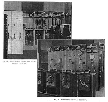
The sub-stations are fireproof brick structures, each containing a high-tension switchboard, a 2200-volt transformer and feeder board, and a switchboard for controlling the arc-lighting apparatus. The high-tension board consists of two line panels and one primary transformer panel. The high-tension oil switches are in brick compartments arranged along the wall behind the high-tension panels. The feeder board in the Flushing sub-station is made up of a transformer panel for controlling the secondary side of the step-down transformers, and three feeder panels. The arc board is fed by two sets of three-phase bus-bars at the transmission pressure, and four arc-light transformers are controlled from each panel. The Flushing sub-station also contains five 100-kw. air-blast transformers, one being used as a reserve, which are provided with duplicate sets of blowing apparatus located in the basement. Four 10-kw. regulators are connected in the transformer secondaries, and two 100-light and four 75-light constant-current transformers are arranged in two rows in the center of the room. The Jamaica sub-station contains four 50-kw. oil-cooled transformers and four 6-kw. potential regulators. There are also installed four 100-light and nine 75-light arc-light transformers. A view of the interior of these sub-stations is given by Figs. 14, 17 and 18.
The engineers for the entire equipment were J. G. White & Co., of New York, to whom we are indebted for much of the information herein contained; and we are also under obligations to the 2nd vice-president and general manager of the New York & Queens Electric Light &. Power Company, Mr. J. N. Bissell, for courtesies extended.
