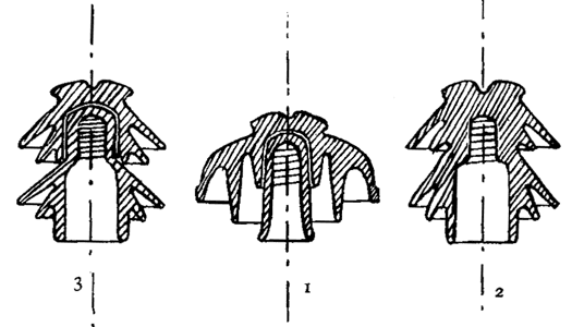
Richard Ginori Insulator for line from Paderno to Milan, Italy
|
[Trade Journal] Publication: Electrical World and Engineer New York, NY, United States |
||||
|
The Paderno, Italy, Transmission Plant. FEW of the many papers presented at the recent Paris International Electrical Congress dealt with electrical engineering from its construction side, but one of this character was of first-class importanceóa paper by Signor Guido Semenza on the practical operation of the large Italian plant for the generation of electrical energy at Paderno and its transmission to Milan and adjoining districts. The paper was read from manuscript, but we are enabled to present some of its main features through the courtesy of the author, who is the electrical engineer of the Societa Generale Italiana di Eletricita Sistema Edison, of Milan, Italy, the company which owns and operates the Paderno plant. The generating station is situated at Paderno d'Adda, some 25 miles distant from Milan, where seven units of 2160 horse-power each are installed, consisting of seven turbines made by Messrs. Riva, Moneret & Company, of Milan, driving seven alternators made by Messrs. Brown, Boveri & Company, of Baden, Switzerland. Three-phase currents are generated at a tension of from 12,000 to 15,000 volts and with a frequency of 42 cycles. This energy is brought down to Milan, where the tension is reduced to 3700 volts. About too substations reduce it again to 160 volts for light and power purposes. In the centre of the town rotary converters are installed, converting the three-phase currents into direct current for light and traction, which latter use absorbs about 2000 horse-power. Experience and accurate observations have demonstrated that the fears entertained by some engineers and manufacturers as to the possibility of obtaining perfect insulation in alternators developing current at 15,000 volts are unfounded. Tubes of micanite 1/4 in. thick have been found sufficient to insulate the windings from the surround-ding iron even at a pressure of 21,000 volts. Only two accidents have thus far occurred, consisting in each case of the formation of an arc between the three bobbins of the three-phase circuit, situated at the lowest part of the machines, the space between the nearest points of the bobbins being 2 ins. This happening could not be ascribed to atmospheric discharges, as in both cases the weather was fine and calm. As accidents of the same nature have occurred to machines of lower potential, a condemnation of a voltage of 15,000 from this cause is consequently not justified. The placing in parallel and the simultaneous working of the alternators have never given rise to any trouble whatever. The coupling can be effected with no load and with the greatest ease, which implies an extremely satisfactory working of the turbine governors. The distribution of the load is effected by means of small motors, which act on the governors and which are worked from the switchboard. It is also interesting to note that the alternators at Paderno, driven by turbines, work with perfect regularity when coupled with those at the Milan station, which are driven by steam engines, although situated 25 miles apart. The efficiency trial of these machines has been made by measuring the losses separately at full load, and they have been found to aggregate about 5 per cent, subdivided as follows: Mechanical losses, 1.25 per cent; copper losses, 1.15 per cent; iron losses, 2.50 per cent; excitation, 0.10 per cent. The efficiency was found to be 4 per cent, with a power factor of .8, the drop at full load being about 6 per cent for cos ∆ = 1 and about 15.5 per cent for cos ∆ = 0.8. The exciters are on the generator shafts, and while the regulation is rather difficult at small load, it is satisfactory near the normal load. Special care has been taken in the construction and arrangement of the switchboard, which covers an area of about woo square feet. Its most important elements are the switch and the fusible cut-outs. The quick-break switch in oil has proved to be very successful, as it allows the interruption of a current of 500 amperes at 15,000 volts with no other effect than a very small spark in the oil. On the contrary, the fusible cut-outs have not given satisfaction, for, besides not being easily calibrated, the metallic vapors which arise at fusion frequently cause an arc from one connection to another, resulting in serious short circuits.
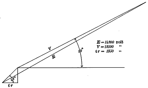
The main line is formed of 18 copper wires, 3/8 in. diameter, carried by two rows of poles 79 ft. apart. Each row carries 9 wires, so arranged as to occupy a series of equilateral triangles. By this arrangement a workman may work on half the line without danger, while the other half is in service. The poles, which are of iron, have led to no trouble, as was generally feared, when proper and suitable insulators are employed. Several tests have been made on different types of insulators by means of a transformer giving up to 50,000 volts. Under such test the German types were discarded, and the very open and largest American type selected. Three varieties of this type are used on the line, designed by Engineer Semenza and manufactured by Messrs. Richard Ginori, of Milan. The first consists of two parts separately constructed; the second represents all that can be desired with reference to shape to prevent disruptive discharges, and the third type is a combination of the two former. One thousand seven hundred and fifty of the first type are employed, and none were rejected on test. Of the second type 3500 are employed, and but 6 were perforated on test. A complete series of measurements has been made to determine the working condition of the line. Measurements of this nature are not easily made, considering the quantity of energy passing and the high working tension. A portion of these measures refer to the determination of the load and to the resulting power factor. These were made on the bus-bars of the transforming station in Milan at the outlet of the cables forming the network system at 3700 volts, with a distribution of 3930 kilowatts, subdivided as follows: 827 kilowatts in the east part of the town, almost totally absorbed by synchronous motors, with a power factor of .76; 1150 kilowatts in the west part of the town, under the same condition of load the power factor was 0.65; 5345 kilowatts absorbed by generating motors for traction and lighting purposes using direct current ; the synchronous overexcited motors had a leading current corresponding to cos 0 = 0.83; 608 kilowatts for electro-chemical industries, with a power factor of 0.70. It is here well to note that manufacturers quote cos ∆ = 0.85 and cos 0 = 0.90 as factors guaranteed, though in practice it is found that motors working on full load are very limited. It must be noted also that in Milan the distribution is very much subdivided, the small motors being greatly preponderant. Besides, one must give due weight to a possible influence of transformers reducing the tension from 3700 to 160 volts. With the values above named it is found that the total current lags an angle corresponding to cos ∆ = 0.91, and that the synchronous overexcited motors exercise a very important action. The influence of the principal transformers on the displacement of phase has been calculated at from 0.91 to 0.89. In these conditions we have: Voltage at the generating station, 14,300 volts; voltage at the receiving station, 12,500 volts; current, 80 amperes. As the resistance of each wire was at that moment 9.6 ohms it follows that: The voltage drop = 12.6 per cent; energy loss = 10.4 per cent. The drop in voltage is then 1.35 times greater than the ohmic loss. With cos ∆ = 1 we would have: Voltage at the generating station. 13,650 volts; voltage at the receiving station, 12,500 volts; Current, 64 amperes; voltage drop, 8.4 per cent; energy loss, 7.9 per cent. The angle of lag due to the line is then 43 degs. This angle measured by the method of short circuiting the line was found to be 40 degs. The capacity current absorbed by the line presents very marked variations depending upon the form of the curve. In normal working for 12,000 volts (42 cycles), 1.03 amperes were found. To divide this current into the two component elements, namely, the capacity current and the leakage current, Mr. Semenza adopted an ingenious method, which consists in inserting between two wires of the line a lamp resistance and measuring, with the aid of three ammeters, the current absorbed by the line, that of the lamps and the resulting total, which form a triangle in graphical representation. Separating the current absorbed by the line into two components, one parallel to the e. m. f. (determined by the current in the lamp) and the other in quadrature with it, he found 0.24 ampere to be the value of the leakage current, and 1.008 amperes the value of the capacity current.
The greatest care must be taken to protect the lines from atmospheric discharges, and Mr. Semenza furnishes some interesting information on this point. At the extremity of the lines a number of Wurts lightning arresters are installed and along the line groups of Siemens lightning arresters. Heavy storms were frequent during the year 1899 and also in the present year. The interruptions of service due to this cause have been four in number, and but two of these have been ascribed to faulty working of the lightning arresters. Seldom more than four or five discharges occur during a storm. Whether this is due to local conditions, to the protecting action of the iron poles or to the type of the lightning arresters, the slowly and continuously discharging of which prevent the accumulation of static charges, is yet to be ascertained. The Siemens lightning arresters have acted properly several times, although their discharges cause a considerable lowering of tension, which may possibly provoke the falling out of step of synchronous motors. Mr. Semenza thinks that in general it is almost impossible to foresee or prevent accidents which occur on lines of very high potential on account of their instantaneousness, and earth indicators have seldom been of any real service. Generally the motors that are in circuit at the instant when a short circuit is formed stop instantaneously and become so many short circuits themselves. In such contingencies the only possible thing is to immediately shut down the excitation. With reference to disturbances in telephonic lines, so common in installations like the Paderno-Milan installation, caused by lines at high potential, Mr. Semenza ascribes them to electrostatic induction. After careful observations and tests he found, in fact, that the line assumed a difference of potential to the earth of about 250 volts through electrostatic induction, and that every trouble ceased by insulating very carefully all the telephone circuits. Mr. Semenza closed his interesting paper by a reiteration of his opinion as to the perfect practicability of high potentials, which opinion was shared at the congress by M. Hillairet, president of the section before which the paper was read, who stated, moreover, that the Paderno installation is a model installation in every respect.
|


