[Trade Journal]
Publication: Journal of the Society of Glass Technology
Sheffield, England
vol. 17
ABSTRACTS AND REVIEWS
·
·
VIII. — Glass Feeding, Forming and Conveying Machines.
·
·
122. Pressing Glass Insulators Automatically. WHITALL TATUM CO., New Jersey, U.S.A.— (Assignees of D. I. DUBOIS, Millville, New Jersey, U.S.A.) (Brit. Pat. No. 378,977, May 11th, 1931, No. 11,312/32. Convention date, June 21st, 1930. Divided on 378,856. [Class 56.] Group 23). (From O.A.S.) — Relates to an automatic press which is intended particularly for producing electric insulators of the kind in which each insulator has an internally- screwed socket. According to the invention, the machine consists of a continuously rotatable support for a number of pressing units, a mandrel co-operating with each mould for forming internally-screwed articles, screw-out mechanism for withdrawing the mandrels from the moulded articles, and a continuously driven device to which the screw-out mechanism can be clutched for effecting withdrawal.
 |
| Fig. 44 |
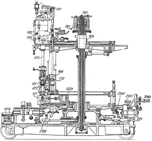
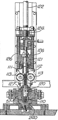
Each of the pressing-units comprises a mould 57, Figs. 44 and 45, the body of which is made in two parts, hinged together, that close around a bottom plate 240 and are opened and closed by an air-cylinder 229. The pressing-plunger consists of a screw peg 110 secured to the lower end of a stem 111, which also is a screw having the same pitch as the peg 110. The stem 111 is rotated by a gear-wheel 121, secured to its Upper end. A sleeve 112 surrounds the stem and carries at its lower end a petticoat 120 for forming the interior of the insulators. The thread on the stem is engaged by a pair of worm-wheels 113 which pass through a slot in the sleeve 112. The wheels are frictionally prevented by means of springs from rotating freely. The screw plug 110 is moved vertically by the piston rod 122 of a compressed air cylinder 134, and the piston-rod also carries a spring-plate 124 which supports the mould ring 127, springs 126 being provided to force the mould ring downwards. The piston-rod 122 is hollow at its lower end and telescopes over the peg stem 111 in order to allow the plate 124 to continue to move downwards when the mould ring 127 rests on the mould. The downward movement of the stem 111 is permitted by the rotation of the wheels 113 against frictional resistance. The piston-rod 122 extends upwards through the top cover of the cylinder 134, and a roller carried by a slide frame 137 can engage the upper end of the rod to limit the upward or return movement of the press mechanism. The frame 137 is kept in position by a spring, but it can be moved horizontally, to allow the pressing mechanism to rise by means of a cam.
 |
After the glass in the mould has been pressed, the peg 110 is screwed out of the glass before the ring plate 127 is raised from the mould. This is effected by a gear-wheel 172 which engages the gear-wheel 121 on the peg 111 and is mounted on a vertical shaft 168. This shaft is coupled to the driving-mechanism at the required times by means of a clutch 169. When the gear-wheel 121 is rotated, the frictional resistance of the worm-wheels 113 is sufficient to prevent them from rotating, so that the stem 111 screws the peg 110 out of the glass article in the mould.
·
·
