[Trade Journal]
Publication: Journal of the Society of Glass Technology
Sheffield, England
vol. 10, no. 40, p. 159,290,335-336
ABSTRACTS AND REVIEWS
·
·
X. — Machinery, Moulds, and Tools.
·
·
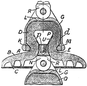
654. Electric Insulators. R. HADDAN, London (CORNING GLASS WORKS, U.S.A.) (Brit. Pat. No. 248,934, March 30th, 1925; from Ill. Official J. Pat. No. 1946, May 5th, 1926). — A method of making a high tension electric insulator, of the kind having an embedded suspension pin, consists in pressing the pin into plastic insulating material to embed it therein, and then moving the pin relatively to the material to form a space between them. The insulator comprises a body, A, Fig. 216, of some suitable insulating material, which may be bakelite or the like, but is preferably a low-expansion glass, such as the glasses described in Specification 100,738. It has a skirt, B, with depending petticoats, C, and a knob, D, of which the lower portion, d, is bevelled inwardly to provide a neck portion, E. A cap, G, fits over the knob, D, and screws on to a ring, K, which is made in two semicircular parts that fit around the neck, E. A gasket, L, of cork or other suitable material, is inserted between the cap and the top of the knob, D, and a gasket, M, of lead, solder, or other soft material is interposed between the ring, K, and the bevelled portion of the knob. The suspension pin, B, comprises a head, P, having a depending shank, p, which is screwed into a lower part, B. The head is preferably of conical shape, but it may be of other shapes so long as the head is larger than the opening in that part of the insulator surrounding the pin. A gasket, U, of lead or solder is interposed between the head and the insulator to cushion the head and to distribute the load. The pin may also be made in one piece.
 |
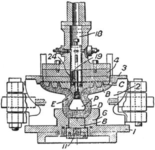
| Fig. 215. |
 |
| Fig. 216. |
A device for making the insulators of glass comprises a pressing plunger, 4, Fig. 216, and a mould having a two-part body, 2, a base, 1, and a removable ring plate, 3. The base has an upstanding boss, 6, which is bored axially to receive a valve, 8, that can be raised or lowered slightly by means of an eccentric, 11. The plunger, 4, has an axial bore, 18, containing a carrier, 19, into the lower end of which the head, P, of the suspension pin is screwed. After the insulator has been pressed, a rod, 24, is turned to detach the pin, P, and the plunger is lifted. The mould is then covered by a jig somewhat similar in construction to the plunger. The cam, 11, is turned to lower the valve, 8, and the pin, P, is pressed farther into the glass, the movement of the valve, 8, leaving space for the movement of the glass. After removal of the jig, the pin, P, is left embedded in the glass but spaced from the sides of the cavity, Molten lead or solder is poured around the pin, after the glass has been annealed, to form the gasket, U, Fig. 216.
·
·
