[Trade Journal]
Publication: Journal of the Society of Glass Technology
Sheffield, England
vol. 13, p. 28,36-37
ABSTRACTS AND REVIEWS
·
·
VIII. — Glass Feeding, Forming and Conveying Machines.
·
·
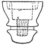
62. Glass Manufacture. B. T. HEADLEY ; D. I. DU BOIS; B. H. KOOB; F. H. LOBB : all in U.S.A., Assignors to THE WHITALL TATUM CO., U.S.A. (Brit. Pat. No. 297,794, Aug. 3rd, 1928. Convention date, Sept. 28th, 1927, not yet accepted; from Ill. Official J. Pat., No. 2079, Nov. 21st, 1928). — A press, particularly intended for making electric insulators having an internal screw thread as shown in Fig. 29, comprises a number of moulds mounted on a rotary table, and each mould is provided with a plunger, or plug, which is forced into the mould by a press head and is afterwards screwed out of the finished article by a separate device, the article being left in the mould ready to be removed by a take-out device.
 |
| Fig. 29. |
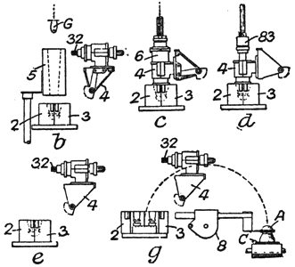
The formation of a glass article is illustrated diagrammatically in Fig. 31, which shows the operations carried out at a number of the stations to which the mould is carried by the rotation of the machine table. At station, b, a mould, 2, 3, receives a "gob," G, of glass from a feeder, a guiding-funnel, 5, being used to direct the "gob" into the mould. A mould head, 4, pivoted about the mould, carries a screw-threaded plug, 32, which presses the glass and forms the internal screw thread. At the next station, c, the mould head, 4, descends on to the mould and the article is formed by means of a press head, 6, operated by a compressed-air cylinder, which forces the plug, 32, into the mould. At the next station, d, the mould is brought under a chuck, 83, which screws the plug out of the mould. ,At station, e, the mould head is swung upwards, and at station, g, the finished article, A, is removed from the mould by a take-out device, 8, and is deposited on a conveyor belt, C.
 |
| Fig. 30. |
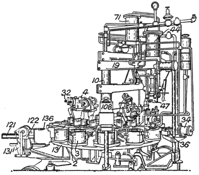
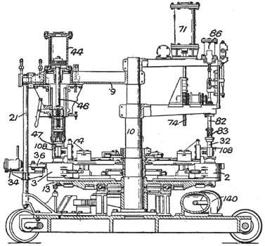
The moulds are each made in two parts, 2, 3, hinged together and mounted on the table, 13 (Figs. 30 and 32), which is rotated step-by-step about a central column, 10, by means of a compressed air cylinder, 140. The moulds are opened and closed by cams fixed to the central column, and when beneath the press head, the halves of a mould are clamped together by means of a toggle clamp, 36, which engages lugs on the mould and is actuated by an air cylinder, 34. A mould head, 4, pivoted above each mould, carries a housing, 108, through which a press plug, 32, slides. The plug is formed with a thread of the pitch required in the finished article, and it engages two worm-wheels mounted in the housing, 108. The wheels are free to rotate, but are braked by spring-actuated friction plates. They rotate when the plug is thrust downwards by the press head, but the braking force is sufficiently great to prevent them from moving when the plug is rotated to screw it out of the mould, so that removal of the plug does not put any strain on the thread formed in the glass article. The mould heads are moved to and from the moulds by means of slides operated by cams on the central column, 10.
 |
| Fig. 31. |
The press plugs are forced down into the moulds by an air cylinder, 44, secured to a framework, 19, 21, its piston rod, 46, carrying a press head, 47. When the press head rises, after a downstroke, the plugs, 32, are left in the moulds, which are then carried by the table beneath the screw-out mechanism. This consists of a chuck, 83, carried at the lower end of a rod, 82, which is reciprocated by an air cylinder, 86. The cylinder lowers the chuck so that it engages the upper end of a plug, 32, and another air cylinder, 71, then moves a rack, 74, which causes rotation of the rod, 82, and thus screws the plug out of the mould. The chuck then rises, the mould head, 4, is swung upwards as the table carries it away from the screw-out mechanism, and the mould is opened and brings the finished article into position to be engaged by the take-out device. This consists of fingers, 136, carried by a rack, 121, which slides through a rotary frame, 122. An air cylinder, 131, first causes the rack to move inwards so that the fingers, 136, engage the finished article, then rotates the frame so that the article is swung in a vertical plane from the mould to a conveyor belt, and then withdraws the fingers and swings them back to their original position. The machine is preferably operated by compressed air, and timing valves are provided to synchronise the different movements of the machine. Safety devices are provided to prevent damage in the event of the failure of the air supply or of the moulds being jammed by pieces of glass. Temperature cooling agents used are liquid air, in which the metals are immersed, or a current of cold an: at a temperature of — 140° to — 170° as it issues from the expansion engine of a gas liquefying plant.
 |
| Fig. 32. |
·
·
