Grand Rapids and Muskegon Railway uses granite third rail insulators
|
[Trade Journal] Publication: Western Electrician Chicago, IL, United States |
|||||||||
|
Grand Rapids, Grand Haven and Muskegon Railway. One of the recently completed interurban electric railways in the West is the Grand Rapids, Grand Haven and Muskegon Railway. This road is representative of high-grade construction, embodying the results of much valuable experience obtained during the course of the construction of similar railway properties. The main line is approximately 35 miles in length, and extends from Grand Rapids, the western metropolis of Michigan, to Muskegon, a thriving manufacturing city of 30,000 inhabitants, situated on the shores of Muskegon Lake and Lake Michigan. A branch line extends eight miles in a southwesterly direction, connecting Grand Haven Junction, on the main line, with the summer resort at Spring Lake and with Ferrysburg and Grand Haven. The latter is a manufacturing city of 5,000 inhabitants, located near the lake shore, and both Grand Haven and Spring Lake are excellent locations for summer residences.
The railway closely approximates the steam railroad, both in territory served and quality of equipment. The road was designed for passenger, express and local freight business. Not the least important item in the acquisition of a passenger business is the improvements which have been undertaken for the purpose of converting Spring Lake into a desirable summer resort. Although the cars of this road will stop at any convenient location for passengers, it has been the endeavor to localize passenger and freight business as far as possible, and to this end nine stations have been erected along the line of the route. These are combination passenger and freight stations, with the exception of those at Walker and Coopersville, which have an independent compartment for the reception of sub-station machinery. The permanent way has been located with exceptional care, avoiding all severe grades and sharp curves, and provides a route between the main termini more direct, by one and 17 miles, respectively, than those afforded by the two existing steam roads. No attempt has been made to follow the highways, and the road operates upon a private right-of-way for the entire distance, with the exception of short stretches through some of the larger towns, where the highway is traversed. The main line is single track throughout and sectioned by frequent turn-outs. The track proper is constructed of 70-pound standard T-rail, double-bonded, standard cedar ties and gravel ballast. Spring frogs and long-point switches are provided at all turnouts, which are all of the single-curve or through-line type. Grade crossings have been avoided, and all railroad tracks are spanned by steel bridges of special design. The earthwork bridge approaches are extended for some distance back, for the purpose of securing an easy grade for the interurban cars. Not the least interesting feature of this road is the employment of the third rail instead of the trolley or overhead system of distribution. Through several towns and cities, where third-rail crossings are impracticable, short sections of overhead have been erected, but, outside of termini, these aggregate less than 2,500 feet in length. The third rail used is 65-pound standard T section, and is mounted upon reconstructed granite insulators. These are bolted to every fifth tie, which is of extra length for this purpose. The rail tread is approximately six inches above and 19 inches distant from the outer rail. At all highway intersections the crossing is protected by cattle-guards and the third rail is broken, suitable wood approach blocks being attached to the free ends, to allow passing contact shoes to regain their bearings without undue shock. The two sections of the third rail are connected by two 250,000-circular-mil copper cables, securely bound to the rail web and carried beneath the crossing in a creosoted wood-pipe conduit filled with pitch. This method of insulating the third rail has proven entirely satisfactory, and the leakage there-from during wet weather is unnoticeable. The bonds used on the track rails are crimped copper-web bonds with solid heads expanded into a reamed hole by a screw compressor, and are entirely concealed underneath the splice plates, two bonds being provided at each joint, in order to avoid pinching by the splice bar. The third rail is bonded with two 350,000-circular-mil flexible copper bonds, applied by a combination hydraulic punch and compressor.
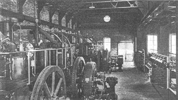
The main power-house building is constructed of brick and steel, with tile roofing, and is thoroughly fireproof throughout. Engine and boiler rooms are of approximately equal size and are separated by a brick partition wall, strengthened by pilasters. The boiler room is provided'with a monitor and skylights for purposes of light and ventilation, which, in the engine room, are accomplished by skylights and ventilating hoods in the roof. Floors are entirely of concrete, that of the engine room being arched between supporting beams to provide for a basement for the accommodation of cable work and pumps of the condensing system. Coal is brought in upon an elevated coal siding paralleling the boiler room. The tracks are mounted upon a masonry and steel supporting structure, beneath which are concrete-lined storage bins of 500 tons' capacity. These bins are accessible from the boiler room through openings in the wall directly opposite each stoker. Four 250-horsepower vertical-header Babcock & Wilcox water-tube boilers furnish the steam supply of the plant, at a pressure of 160 pounds, provision having been made for a future battery. The boilers are fitted with Roney mechanical stokers, which are driven by small Westinghouse standard engines located between the boilers, and are supplied with coal by direct shoveling from the storage bins. The waste gases discharge into a brick and steel flue in the rear of the boilers, thence successively through an improved circulating-type economizer, vertical tandem exhaust fans, uptake and a short steel stack, extending about 15 feet above the roof. Provision has been made in the engine room for six 250-kilowatt main generating units, of which five have already been installed. These units consist of 18 and 30 by 16-inch Westinghouse vertical-compound condensing engines, direct-connected to 250-kilowatt Westinghouse generators, two of which are 390-volt, three-phase alternators and the remaining three double-current machines, furnishing both 650 volts direct and 390 volts alternating current. The grouping of the machines places three units of each kind on each side of the center of the engine room, where are located two 37 1/2-kilowatt exciters, direct-connected to Westinghouse compound engines, running upon the condensing systems. The electrical equipment other than the generators is entirely contained in a fireproof wing, adjoining the engine room and symmetrical about its transverse center line. In the openiner provided by the absence of the dividing wall are located the two main switchboards, which are placed directly upon the wall line, thus preserving the rectangular shape of the engine room. Behind the switchboards is installed all high-tension apparatus. In the basement is the transformer vault, which will eventually contain seven 400-kilowatt Westinghouse oil-cooled transformers, four of which are at present installed, one as a reserve only. These are delta-connected and raise the bus pressure of 390 volts to a line pressure of 16,600 volts for transmission. On the first floor of the transformer room is located the entire high-tension switching apparatus. The high-tension switches are of the Westinghouse pole-fuse type, and are operated from a low wooden insulating platform for security against accidental shock. Above these switches is the lightning protective apparatus, mounted upon heavy marble panels and connected with static interrupters upon the main floor. The transmission wires lead directly from these panels through heavy glass insulating wall tubes to an anchorage outside of, and secured to the wall and thence to the line. All connections between transformers, switches and arresters are of lead-covered cable, with heavy rubber insulation. The low-tension board is divided into alternating-current and direct-current sections, erected upon either side of the center line of the transformer wing. One board contains 500-volt direct-current apparatus only, and controls the direct-current side of the double-current generators, the 125-volt exciters and the local feeders, while the other board controls the alternating-current machinery and transformer primaries. The boards are of Westinghouse design and embody the latest types of indicating and recording meters, quick-break switches, circuit-breakers, time-limit relays and synchronizing apparatus. The generating machinery operates in parallel, the units being synchronized by the control of the engine throttle and the indications of a round-dial synchroscope. A complete system of compressed-air piping and storage tanks provides four 62-foot B. and S. combination baggage and B. and S. parlor car; same equipment, with rich efficient means for cleaning the electrical apparatus. The distribution system is supplied with power from three points, viz., the main station and the two sub-stations. The district near the power house is supplied'from the direct-current side of the double-current generators, while the sub-station rotaries feed the remainder of the line. The two sub-stations at Coopersville and Walker are, respectively, 12 and 22 miles distant from the power station at Fruitport. They are combination passenger, freight and sub-stations, and are constructed and equipped along the same general lines as the power station. Each station is provided with a fireproof high-tension tower, in which is isolated all high-tension apparatus in the same consecutive arrangement as that employed at the main station. This arrangement evidently permits the use of a much lower building than would otherwise be possible, and adds largely to its attractiveness. Fifteen thousand-volt current is led into the sub-station towers from the transmission line through heavy glass wall tubes to the high-tension fuse switches, which are mounted upon the wall of the tower, within easy reach of an operator standing upon the elevated high-tension gallery. The current then passes through openings in the concrete floor to a bank of bayonet switches, thence continuing to the transformers resting on the ground floor of the station. The bayonet switches were provided for the purpose of isolating a defective or damaged transformer. The employment of the delta connection of transformers admits of this without disturbing the operation or phase relation of the line, the remaining two transformers being able to carry the increased load for a limited period. Lightning protection is identical with that of the main station and is completely isolated inside the high-tension tower. Each sub-station equipment comprises two 250-kilowatt rotaries, with starting motors, three 200-kilowatt, oil-cooled lowering transformers and a six-panel white marble switchboard.
As in all work of this character and magnitude, the train sheet has been the basis of all determinations for locations of stations, power equipment and line conductors. Owing to the use of the third rail for the major part of the distance, no extra copper feeders were necessary, the rail having ample cross-sectron to carry the entire current. Where bracket or span-wire overhead construction was necessary, 500,000-circular-mil aerial feeders and No. 0000 B. & S. hard-drawn grooved trolley wires were provided. The main transmission line is carried upon 30-foot cedar poles, set six to seven feet in the ground, and is provided with a single-braced crossarm, which supports two of the three wires. The third wire, forming the apex of an equilateral triangle, 28 inches upon a side, is supported by a special "ridge-iron" pin, mounted upon the pole top. Proper line insulation is secured by five-inch umbrella-type porcelain insulators. All poles carrying both trolley and high-tension wires are five feet longer than the regular 30-foot high-tension poles, in order to prevent possible contact of the trolley with a live high-tension circuit. Brackets are constructed of two-inch steel pipe, with malleable fittings, upper truss rod and steel span wire carrying a single "round-top" straight-line hanger. The telephone system has been installed with the greatest care and embodies the most substantial construction. In the open country, telephone wires are carried at a height of 14 feet upon a line of 20-foot poles, where no transmission line runs, and upon the high-tension pole line within the transmission district. The circuit is metallic, of No. 8 B. & S. hard-drawn copper, and at all sidings taps are brought down to waterproof jacks, conveniently located upon the pole for purposes of telephonic connection. Interference from alternating-current induction, in both high-tension and telephone lines, is prevented by transposition of leads at regular intervals, and lightning protection is all concentrated at the stations, none being applied along the line of route on account of the difficulty of maintenance. The rolling stock comprises 15 52-foot Barney & Smith passenger coaches, three 40-foot express cars and one construction car, furnished with tools, snow-plow and a motor-driven winch. The passenger cars contain 28 double, non-reversible seats, upholstered in red plush, and are finished in white oak and holly, with plate-glass windows, doorlights and bulk-heads. A smoking compartment is provided in the front part of the car, which is ventilated by a suction draft induced during motion of the car by the curvature of the front vestibule. Electric heaters are provided throughout. A complete telephone set on every car enables the conductor to obtain instant communication with the despatching station by means of flexible cord and plug which fits into the telephone jacks located at all sidings and stations. Special pole connections are also provided on all cars, so that in the event of accident or disablement at any point on the line, telephonic communication with the despatcher may be had at once from the car. Passenger cars are equipped with two 150-horse-power Westinghouse No. 50-C. motors, both applied to the rear truck by Gibbs' suspension. Trucks are of the M. C. B. type, built by the Baldwin Locomotive Works, and driving wheels are steel-tired, while those of the leading truck are spoked wheels with chilled treads. Express cars are similarly equipped with two Westinghouse No. 76 motors. The construction car has one No. 76 motor per axle, aggregating 300 horsepower in addition to the winch motor. This equipment enables the car to make emergency runs and perform all kinds of heavy duty such, as wrecking, hauling gravel cars, pile-driving and snow-plow work. All cars are equipped with Westinghouse air brakes, supplied by type-D motor-driven, reciprocating air compressors, placed under the car body and controlled from the vestibule. Cars are dispatched by telephone from a station located at Fruitport. They operate at an average cross-country speed of 35 miles per hour, with a headway of 30 minutes. Lay-overs of six to 10 minutes at termini and car barns are provided in the schedule, allowing ample time for making reports, inspecting wheels and journals, filling sand boxes, etc. Express service is as yet seriously delayed by the lack of terminal facilities, but it is expected that regular express service will be started in the near future. The Grand Rapids, Grand Haven and Muskegon commenced operation in the early part of the year and has been uniformly successful in establishing a permanent and lucrative traffic throughout its territory. Although greatly handicapped by the lack of suitable terminal stations, the road at once placed itself upon a dividend-paying basis, thus demonstrating the wisdom of thorough construction. The road was located, designed and constructed through-out by Westinghouse, Church, Kerr & Co., and represents their latest practice in the railway field.
|