[Trade Journal]
Publication: The Journal of Electricity, Power and Gas
San Francisco, CA, United States
vol. 13, no. 1, p. 46-55, col. 1-2
SUCCESS IN LONG-DISTANCE POWER TRANSMISSION.
BY F. A. C. PERRINE, D. Sc.
TWO elements make success in the long-distance electrical transmission of PowerContinuity and Regulation. Perhaps these are the most important elements in any electrical undertaking and are the most obvious, but in attaining our ideal in long-distance work, there lurk pitfalls about these two elements unknown in other fields of the art. From the outset in the original studies, and down the line to the last switch and insulation, lie unknown problems and problems known, but unsolved. It is the field of the thoughtful, independent engineer; the ground is stony and fit traveling only to the most resourceful.
 |
| Diagram of Connections of the Bullock Type F Sychronizing Indicator Used in the 10,000-Volt Motor-Generator at Colton. |
Hydraulic development is one of the oldest arts, but the amount of human ignorance concerning hydraulic problems and conditions is appalling. Records may have been kept of the rivers whose waters are navigable, or whose rapids and falls are along the railroad lines, or in the manufacturing villages; but an investigation of the records available concerning important powers, even a few miles out of the regular lines of travel, would surprise you by their lack of accuracy and detail. Rainfall has been kept for generations for the benefit of agriculturists, but the watershed of no one power steam of my acquaintance has ever been completely covered in its essential details by rainfall records. The water available at any one point where the rainfall can be approximated will be estimated by different engineers from 15 per cent, to 70 per cent, of the total fall, and, apparently, each will be justified by engineering precedents. Such possible variations call for the exercise of caution, judgment, and experience in reaching conclusions.
| |||
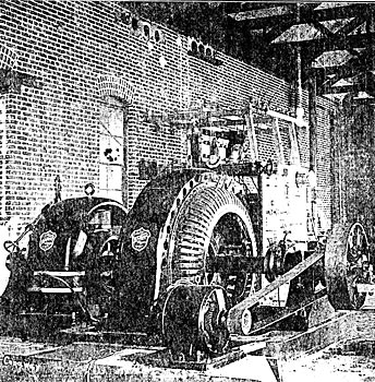
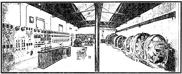
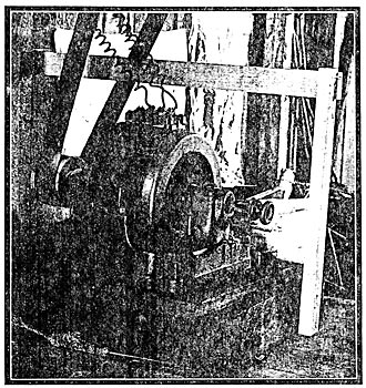
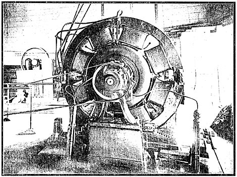
| The 10,000 Volt Bullock Motor-Generator Set Operating the Railway System of the San Bernardino Valley Traction Company. |
Nor is there less uncertainty in regard to hydraulic construction. The present year has seen the failure of dams built by engineers of the highest reputation and at water pressures for which they were supposed safe. The flow in canals, ditches, flumes, and pipes are still subjects of dispute, and errors in design are continually leading to serious results for the investor. The one lesson to be drawn from all this being that, if continuity only means success, the studies in water-power location must be made with unusual care, and ample, though never ridiculous, margins allowed in the estimates.
 |
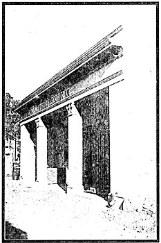
| Method of Taking 10,000-Volt Lines Into Building. |
Perhaps the day may come when the civil engineers will establish their empirical equation in hydraulics on a sure basis, but until that day is reached, and it is not near, the hydraulic engineer can never cease to be a student and most careful observer. In almost all cases the formula; of engineering have a sound experimental foundation, but the error has actually been made of attempting to apply results obtained from the gaugings of the Mississippi to small rapid rivers, and even in some cases to lined canals and timber flumes, and an equal error committed of attempting to apply the results obtained from the flow of water in eight and ten inch pipes to great conduits and even open flumes. No smile should arise over the absurdity of these errors, for every State in the Union has instances of them, and no year in the past twenty but has seen them committed to the waste of thousands and hundred of thousands of dollars. The records for the past five years at one of our most respected testing flumes are at fault on account of an altered pressure pipe and an unconnected formula. Success comes to the cultured engineer who keeps close to his borrowed data and who solves for himself the unforeseen problems.
I mean by "culture" what Matthew Arnold means when he says that culture is "A pursuit of our total perfection by means of getting to know, on all the matters which most concern us, the best which has been thought and said in the world." Such an engineer with such an ideal will be a safe guide and his studies will establish on a firm basis our transmission undertaking.
 |
| Type of Substation for Less Than 100 Kilowatts Capacity on 10,000-Volt Systems of the Edison Electric Company |
But we are not concerned at the present moment with the errors of the civil engineer, or with his unsolved problems, so much as with what is new and with what is gradually getting to Ire known in electrical problems. While these are no more important nor more interesting than the hydraulic problems, they are attracting more attention, and perhaps it is in apology for our electrical ignorance that I call attention to hydraulic difficulties and ignorance. It is true that in no other art can so accurate calculations be made as in electrical engineering, but there are many facts and constants for our equations still unknown. Even in the electrical art there is still an unknown, and I suppose that no one of us will live to see the discovery of even all the knowable our art contains. I am reminded now of the beautiful equation for the dynamo machine presented twenty years ago by Clausius, which contained a round dozen of unknown constants, others have been found to have been variables, and we are still studying the problem and searching for the others.
Regulation in direct current work is a simple problem. Its laws are all known; at every lamp it is quite easy to predict the variation of voltage. The same laws control whether the lines lie long or short. In his transmission plants Thury has met no new difficulties but has effected regulation at ten or twenty miles, just as he would have done had the delivers' been made only in the next room to his dynamos. Resistance is always resistance and his dynamo characteristics remain unaltered by its increase. He deals only with current, voltage, and resistance and encounters problems simple even to Faraday, Henry, or Ohm.
It has been said very truly that the introduction of the alternating current raised the electrician above the rank of the artisan. With these currents he is no longer dealing with a few simple independent quantities connected by a primary rule, but must now consider many new elements, some constants and some variables. At every step capacities and self-inductions enter in the solution in complex and involved relations. Regulations can no longer be simply determined for each part of the system independently, and the regulation of the whole obtained by a consideration of the parts separately. Self-inductions and capacities affect each other, and the generators and lines, as well as the transformers and motors must be chosen or designed with this independent relation in view. A simple case illustrates this beautifully.
When the operation of the transmission supplying current to the city of Stockton, California, from the power plant at Mokelumne Hill, forty-six miles away, was first begun, a curious state of affairs was observed. In the operation of the lines alone, the current required on the 2200-volt side of the step-up transformers was sixty amperes; with the step-down transformers connected, the current fell to about fifty amperes, and when a 100-kilowatt motor was put into operation the current was only fifty-five amperes. The transmission was designed to be at 25,000 volts, but at the delivery end of the line the voltage was found to be 27,200 volts, and finally the motors consumed full current when running at no load and not much more when operating with full load applied. I think that all will agree that here are problems enough for one small instance of the difficulties in the regulation of a long-distance transmission plant. The lines in this case had been calculated for an 8 per cent, loss of energy for transmission of 1000 kilowatts and capacity played the most important part in these pranks as to absorb an apparent energy of over 130 kilovolt-amperes. This is reduced when the transformers are connected and some real energy logins to flow and the self-induction of the step-down transformers neutralizes some of the capacity of the line. When the motors are connected, the energy is increased and the self-inductances of the various parts of the system become more important.
The apparent rise of voltage along the line illustrates the interdependence of the whole system even more clearly, for it is only in a very small part due to the line itself, or rather, while due to the line, it occurs in the step-up transformers and not to any extent along the line.
 |
| Type of Substation for Less Than 100 Kilowatts Capacity on 10,000-Volt Systems of the Edison Electric Company |
It is not uncommon to attribute such an effect to resonance, which really only rarely becomes important; in reality, the regulation of the transformer produces this effect. With any transformer fed with a constant voltage at the primary, the secondary voltage falls with non-inductive load and falls still further if an inductive load is applied, but if the load is a capacity load, the secondary voltage rises instead of falls. In this case, therefore, the step-up transformers were delivering a 10 per cent, higher voltage to the line than their transformation ratio accounted for, which necessarily disturbed the regulation seriously. This trouble became even more serious when a heavy induction motor was later operated by the same plant. The load on the motor accounted for a fall of potential amounting to 4 per cent, but the inductance produced a drop of 10 per cent, at least; and, as the rise of voltage on the line at no load was as much as 10 per cent., it may at once be seen that the voltage varied when the motor was connected from 10 per cent, above normal to 10 per cent, below, and thus a variation exceeding 20 per cent, was produced in place of a variation of 4 per cent, for which the load allowed.
The effect upon the synchronous motor was also due to this ever troublesome capacity. The generators were giving nearly a true sine wave of electromotive force while the motors were designed for a peaked wave, the line capacity so affected the generator wave that the difference between the motor and generator became great, and for part of each wave the motor was absorbing power, and for its remainder delivering power, so that always a great current was flowing.
In this particular case these troubles were corrected by the introduction of a heavy self-induction across the ends of the line which neutralized the line capacity; and this self-induction was used until an inductive load was connected in the shape of induction motors, which rendered the use of an extra self-induction unnecessary. Whenever this arrangement can be thoroughly carried out and the capacities and self-inductions connected to any line be evenly balanced, the alternating problem can be reduced to the simplicity of the direct current problem and long algebraic equation abandoned in determination of the expectations. This possibility is beginning to be appreciated and regulation attained in long-distance transmissions which could not otherwise be hoped for.
There is little service which calls for absolutely continuous power. Most plants, which are said to be operating "day and night," shut down at meal times and are rarely operated more than twenty hours of the twenty-four, and even when the operation is continents through the day, there is a cessation of operation on Sundays and holidays. For this reason, it is difficult to satisfactorily balance the capacity of the line against the inductance of any load. The line capacity current is constant and is continuously in evidence so long as the voltage is applied to the line; indeed it varies only with the voltage and periodicity. Its importance increases as the load diminishes, for when the load is heavy it is not only completely overcome by inductance, but also is rendered unimportant by reason of the presence of a large cur- rent in phase with the electromotive force. During the time when all loads are diminished, the disturbance of regulation by reason of the presence of a line capacity-current is most apparent, and consequently the counteraction of that capacity effect, by a heavily inductive load which is off during these same periods, is a remedy which only accentuates the disease. This was illustrated in the case described above where a severe induction load depressed the voltage and its removal allowed the full rise due to line capacity.
In the case of the Bay Counties Power Company's transmission, where transmission of approximately 150 miles at 50,000 volts and 60 cycles are undertaken, the charging current is approximately 40 amperes; or, in other words, the line requires the full capacity of a 2000-kilowatt machine for charging it as a condenser. The complete neutralization of this great capacity effect would require the continuous working of something in excess of 5000 kilowatts of induction motors with average normal power factors. Up to the present time no load on the Bay Counties lines has ever been applied which is capable of neutralizing this capacity effect. The power house is practically unable to have much knowledge of the loads actually applied on the lines except by observing the wattmeters or the wheel nozzles, since the current from no load up to a load of several thousand kilowatts remains practically constant. As there are many branching lines supplied from this system, it is impossible to operate other than with constant electromotive force at the dynamos, and the regulation of the long lines is affected by the capacity, which influences everything from the step-up transformers to the last motor.
| |||
| Exterior View of Substation No. 2 of the Edison Electric Company, Los Angeles, Cal. |
| |||
| Interior Views of Substation No. 2 of the Edison Electric Company, Los Angeles, Cal. |
In order to overcome the troubles due to this source, the Bay Counties Power Company has arranged to place upon its lines impedance coils capable of practically neutralizing the entire capacity of their long lines; and, as soon as these are installed, one of its greatest difficulties in obtaining satisfactory regulation will be removed. With the capacity of the line neutralized, it then becomes necessary to keep the load as nearly non- inductive as possible by continuous care in the balance of synchronous against induction motors in the operation of loads.
It is a great mistake for an engineer to become an advocate of one motor to the exclusion of the other type. Both synchronous and induction motors have their spheres of usefulness, and practically every long-distance transmission demands for its satisfactory regulation the use of both types. Where the powers are small and the loads easily started, the simplicity of the induction motor and ease of installation renders it especially suitable, but as their numbers increase, the effect of the lagging currents they absorb becomes important in disturbing regulation, so that it soon becomes necessary to neutralize this lagging current either by the introduction of condensers or of synchronous motors.
 |
| An Average Chart Showing the Voltage Regulation (9:46 P. M.) During A "Short" on the Main Transmission Line |
With a synchronous motor it is possible to counteract the effect of large and variable inductive loads, and, when they are installed in the substation at the delivery end of the line, a ready and satisfactory means of controlling the voltage, whether it is disturbed by inductive or non-inductive loads, is provided. Practice with these machines indicates, however, that they are still very useful if installed at points out of control of the substation attendants, provided only that their power of controlling voltage be not used maliciously, since they are generally most useful when the exciting current is adjusted to a minimum; a condition for which instructions are easily issued and of which the reasonableness appeals to the most ignorant attendant.
 |
| Arrangement of Strain Insulators |
Much has been written and said of the resonant condition of a line, but up to the present time practice in the installation of plants and connection of motors, transformers, and other devices has not led to important interference from this source. What is called the resonant line, or distortionless line, can be obtained in two ways, either by the connection of capacities and inductance in series, or by their connection in parallel. In the first method of connection there is a very serious rise of potential at the respective terminals of the capacities and inductances, but with the parallel connection no such rise is found. The series connection of capacities and inductances is rarely used, and principally on account of the difficulties likely to be encountered on account of these phenomena. The exact balance of inductances against the capacity of a line fifty or one hundred miles long, capable of supplying some thousands of kilowatts, would result in a voltage rise of not less than ten times the value of the normal; and, when one considers that this normal may be anywhere between twenty-five and fifty thousand volts, it is easily seen that such resonance may be formidable. Such an effect is sometimes actually encountered in the operation of switches on lines where considerable cable lengths are used in feeding highly inductive apparatus. In a recent case an arc within a partially broken cable feeding rotary transformers, by raising the periodicity and producing apparently a resonant condition, caused the effect of most violent short circuits, blowing fuses with great violence and destroying both fuse holders and switches, currents appearing entirely beyond the capacity of the generating apparatus to maintain. When the proper inductances are connected in parallel, however, their action is beneficial to regulation and easy to handle, as has already been explained.
What has so far been said covers fairly well the question of purely electrical problems of regulation, and to call your attention to the essentials of the problem, it only needs the summary that regulation in a long distance plant is attained by
First. A wide possible voltage variation in the generators, with generators and transformers both designed, not for good non-inductive load regulation, but for good inductive load regulation.
Second. Lines designed for the smallest possible capacity current without reference to any attempt at balancing the line capacity against the load lag.
Third. The use of reactance coils for balancing the constant capacity of the line.
Fourth. The use of synchronous motors as a variable capacity or balancing the variable inductance of the line and the inductive motor load.
Of the elements of design which involve most nearly the question of continuity, supreme importance attaches to the insulators, the switches and the lightning arresters.
To be sure, the entire problem of continuity is also the whole problem of design. Everything must be built to withstand the strains, and the methods of accomplishing this are neither easy nor obvious; many of the well established methods of conveying and controlling water must be abandoned in favor of those which are more enduring. Open ditches and flumes are giving way to enclosed and lined trenches and tunnels.
 |
| Method of Hanging and Connecting Transformers on 2,200-Volt Circuits |
For station structures, the extreme of strength and fire-proof character must be resorted to and the whole transmission line must be built for the greatest permanence. Spans are shortened even in some cases to only one third of that used in telegraph and telephone construction. Heavier poles are employed, most carefully set, and braced against even the slightest increase of strain. Rights of way are secured and cleared so that these transmission lines stand up against the storms and fires that lay waste the countryside.
| |||
| The First Three-Phase Induction Motor Turned Out by the General Electric Company Still Runs at Redlands |
| |||
| Induction Motor Operates the Elevator of the Casa Loma Hotel |
But returning now to the purely electrical part of the problem with which we are mostly directly concerned for the present, and directing our attention to the insulators, which present the first and most difficult problem, we find at the outset a royal battle waged between the insulating properties of glass and porcelain. In this country glass has for many years been the king of the insulators; abroad for an equal period of time, porcelain has remained pre-eminent.
For potentials up to about 25,000 volts, where an insulator of seven inches diameter is sufficient, there seems not much reason for the employment of anything except glass, unless the lines reach a size above half an inch in diameter, when its strength is deficient. For these lower potentials and lighter lines the good properties of glass are easily summarized. In the first place, it is cheaper by far; while not so strong as porcelain, it is, as has already been said, sufficiently strong for the purpose; its inspection is easier and surer, since it requires only a visual examination and a few taps of a hammer to ascertain its soundness in place of the tedious high potential test necessary in the examination of porcelain. But having said this much, all has been said that is possible in favor of glass.
 |
| Standard 10,000-Volt Cross-Arm Construction for Long and Short Special Cross Arms of the Edison Electric Company |
It is not true that glass is a better insulator than sound porcelain, nor is its surface so good in damp weather against surface leakage. The mechanical strength does not equal one half that of porcelain, as has been proven by a long series of mechanical tests performed by dropping a steel ball from a height upon insulators of the two materials; temperature also affects it much more than porcelain and it is often found to crack simply from the effect of extreme changes of temperature. The insulators for high voltage lines must be very large, for the reason that with a striking distance through the air of from four to six inches, great gaps must be provided in the path of the current. But above all a great creeping distance is essential.
Insulators that are a perfect protection in the hardest rain fail utterly in clear weather when covered by smoke and soot, which allow small amounts of current to escape and char away the pins or cross-arms. The compound insulator is very attractive, for the reason that it is easier and cheaper to make and handle two or three small parts rather than one large one, and in some cases the additional advantage has been sought of securing the good properties of both glass and porcelain by making parts of an insulator of each; but there is both a theoretical and practical fallacy in this type of design. In the first place, no dielectric is so strong as one entirely homogeneous. As the stress is passed from glass to porcelain, or vice versa, at the two surfaces the stress piles up, as it were, and it is better if one believes in glass to rely upon it; or, on the other hand, to show faith in the porcelain used by employing it entirely.
From the pure standpoint of practice the insulator which must be cemented together is troublesome. The shrinking of the mastic leaves voids and produces strains; if cement be used, its slowness in hardening delays the work and requires large areas for setting out to harden any considerable number of insulators. The one other mastic in use is molten sulphur, which, while better as a mastic than cement, is still more liable to crack the insulators while they are being joined, and when it is exposed to light and air it frequently decomposes on the surface, producing sulphuric acid; and, finally, when current creeps over its surface following the acid, perhaps, catches fire and often results in the rupture and fall of the insulator. The insulator which will be entirely satisfactory for its use has not yet been found, but the diligent search made for it by some of our best engineers is resulting in its definition and will probably soon result in its production, not as an inspiration for a patent, but as a careful engineering conception.
Switching and switching devices are most important and most difficult. Step by step the switch has improved in the electrical art from the simple commutator used by Faraday and Henry, which generally consisted of copper wire dipping into mercury cups; until, as you know, up to the present time a great amount of ingenuity devoted to the study has resulted in the production of elaborate and beautiful electrical and mechanical mechanisms. Switching for high powers, whether at low potential and great currents or at high potential and small currents, seems to lie an altogether different art from switching where the spark that may follow can do but little destruction, and its heat is readily dissipated. Almost all low power switches are designed with the idea that a spark may occur at the break, but as the energy of the spark is small, the mass of the switch will carry the heat, or the portion of the switch destroyed will be inconsiderable and may be easily replaced; hut as soon as it becomes impossible to contemplate the destruction of a portion of the switch in the rupture of the current, switching becomes impossible by such simple devices, the whole art of switching is changed, and designs along entirely new lines must be produced. The great pneumatically controlled switches in the large power stations of New York and Boston exemplify this principle. Hardly anything in switching for small currents is similar. They are not simple switches, giants in size, but their method of operation is based upon a new principle and they involve in their construction much ingenuity and engineering study. As even the great switches with which you are familiar operate only on lines where the potential is comparatively low, the principles of high voltage switching need to be particularly called to your mind. In any high voltage transmission system, as, indeed, in any transmission system, the lines and loads contain not only resistance but also capacity and self-inductance. The current flowing depends on the electromotive force, the frequency, and the constants of the circuit in an involved relation. A change in any one of these constants involves changes in the resultant current. A satisfactory switch must leave the circuit undisturbed as far as possible, and must introduce no new difficulties by reason of changed values of the constants. Furthermore, if a switch could be built which would simply instantaneously stop the current, the effect would be an immediate and great rise of potential due to the sudden fall of current through the capacities and self-inductions of the system. The open air switch, which, in its essential particulars, is simply that of the ordinary knife, or snap switch as used for low potential, draws an arc at almost full current value, which arc, being rapidly oscillating in character, effects an increase of the periodicity on the line and thereby brings about great potential rise. We see, therefore, that a switch to be satisfactory on a high potential circuit must neither rupture the circuit too suddenly nor draw an oscillating arc. With ordinary switches in mind, the rupturing of a circuit with these requirements in view seems to be almost an impossibility; and, were there no means of introducing into the path of the switch blade high resistances which gradually reduce the current value, and finally allow the stoppage of the flow of energy after it has become small in amount, we would have to provide in insulation of our long-distance high-potential lines, materials which would withstand voltages from two to ten times the normal voltage. Of course no wire-wound or carbon rheostat can be introduced into these switches, and the only resistances that are available are liquid and gaseous resistances. It is almost too soon to say that any particular type of switch has resulted from the experiments of the past two years which will be considered for all years to come the final type; but the successful work that has been done is along the line, as I have said, in the introduction of liquid and gaseous resistances. These resistances are the only ones that are high enough in value to be enclosed in the small space of a switch and which do not introduce additional complexities into the station system. The gaseous resistance is obtained in the oil switch by the carbonization of the oil as the switches open; provided there be a sufficient amount of oil above the switch contact, so that as the circuit is opened the production of gas does not blow the oil out of the switch, a very satisfactory type of switch is produced, and one which our present experiments seem to indicate will gradually cause the rupture of a circuit without the production of excessive rise of potential.
| |||
| The Famous Pioneer Three Phase Synchronous Motor Runs the Plant of the Union Ice Company at Redlands. |
The vaporization of metallic oxides has also been successfully used for this purpose, but when these oxides are vaporized in the switch, it is difficult to retain them within the switch and they scatter their dust through the whole station. The liquid switch is one of the comparatively new developments, and seems in many respects to be the best of all, since the liquid is always prepared as a resistance under all circumstances and does not depend upon the energy of the current to make it the imperfect conductor required. Therefore, the disadvantage of the occasional failure of the switch from too rapid or too slow production of the vapor, as is the case with the vapor switch, is avoided. An incident in the difficulty of obtaining the proper switch for high potential working is the difficulty of insulating its moving parts and operating mechanism. Insulation materials of high dielectric strength are not ordinarily satisfactory mechanical materials. They are brittle, they are hard to work, often impossible to work, and are not readily obtained in exact form. Hence, many a switch that is entirely satisfactory from an electrical standpoint proves to be a failure on account of the difficulties with its mechanical support.
| |||
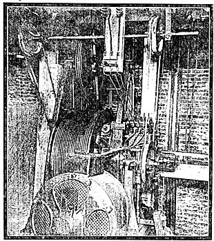
| In the Pasadena Auxiliary Plant and Substation |
Lightning protection for long distance transmission lines is, as one can readily see by the slightest consideration, of the utmost importance. Where a line passes over one hundred or two hundred miles of open country, clipping into the valley and rising to the tops of mountains, all sorts of weather conditions must be constantly encountered. A thunder storm of small area is, in summer time, a matter of frequent occurrence; and when we consider that, as the line stretches way across the country, many small areas of atmospheric disturbances may be and must be daily encountered. To be sure, as you all know, the lightning protection of a transmission line is not against strokes of lightning, but against the induced currents in the line by reason of neighboring lightning strokes. Furthermore, any transmission line must be protected against variation of atmospheric potential in clear weather. Experiments have shown that changes of elevation by a few hundred feet sometimes produce potential variation of many thousand volts and these phenomena must be encountered and handled by the transmission engineer. One of the most effective devices that has been used is the erection of a continuous lightning rod along the entire line. For this purpose barbed wire, grounded at the poles, has been employed. In some instances this has given trouble on account of the fact that the barbed wire used was inferior in quality and erected with unsafe strains; but when the wire has been carefully erected, it is not necessarily a disturbance to the system, but a means of discharging the wire when the atmospheric potential varies and as induced current surgings are set up by neighboring lightning discharges.
| |||
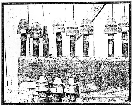
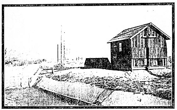
| These Insulators Carried 10,000 Volts for Six Years Near the Colton Cement Works |
It is not by any means a settled principle with transmission engineers to install this barbed wire, though in the South, where the lightning disturbances are most frequent, it may be said that almost every line is erected with this protective device. Where it is not used, reliance is placed altogether on the lightning arresters, through which the line may be grounded, these being installed either at the ends of the line or at the ends and at intermediate points; and even where barbed wire is employed, such additional protective devices are absolutely essential, since the currents themselves can not be entirely freed from induced charges by any means, except enclosing them with a grounded metallic sheath, and this construction would, of course, be absurd and unmechanical. No mechanically operated lightning arresters are ever used for this purpose in alternating long-distance transmission work, the devices employed being either of the non-arcing metal type or of a type where the air current produced by an incipient arc between the parts of the arresters blows out the arc before the machine current has an opportunity of following and affecting destruction. In some devices the combination of these two effects is to be found. These constructions of lightning arrester are old and well tried at lower potentials, but it is found that as the potentials rise, the laws which seem to govern their action change materially, and no step has been made in raising the voltage without requiring material modifications of the rules for the installation of lightning arresters. Two thousand-volt calculations have been found to fail altogether on 10,000-volt lines and these again to fail when the potential was raised to 25,000 volts, and finally with the doubling of that potential, the previously ascertained rules seem to be altogether thrown to the winds, and a new system of lightning protection made necessary. The final form in which this will be received by the engineering world has not as yet been established, but the experiments which have been tried up to the present time, seem to indicate that a resistance or an impedance, or, resistance and impedance combined, must be installed in the path of the ordinary lightning arrester in order to enable the induced charges on the line to pass away readily without noticeably increasing the effective line potential and without grounding and short-circuiting the wires. The handling of this problem has been one of the last to be solved, and one of the most troublesome questions involved in the engineering of transmission lines.
| |||
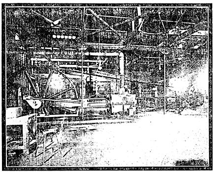
| A Typical Transmission Pumping Station in Southern California |
I have thus been endeavoring to call to your minds the problems met by the transmission engineer, and the difficulties he has to solve, which are not presented to his brethren in handling ordinary electric lines and currents; and though I may have given you the impression that there are many questions yet to be solved in order to bring about success in long distance transmission, when success is measured by practically perfect regulation and practically absolute continuity, still it would be incorrect for me to have given you the impression that the engineers are still groping in the dark for a solution of their problems for the attainment of success as measured by the criteria I have laid down. The limitations I have placed upon the solutions that have been already applied relate only to the question as to whether present solutions are in their final form, and it would be a wonder of the world if, with long-distance transmission beginning in 1894 with a small plant at Portland, Maine, and a small plant at Housatonic, Massachusetts, the solution that has been reached in 1902 for the problem as extended to 200 miles were in the final form; and if I have given you some of the inside history of the difficulties to be encountered by transmission engineers, you would be doing me and those engineers an injustice to believe that I have been doing anything excepting calling to your attention the difficulties that have been met and the construction which still remains to be improved, while at the same time announcing the triumph in practically and successfully transmitting power up to 215 miles, and practically and successfully building at least two plants for the permanent distribution of energy at distances in each plant exceeding 150 miles.
THE EVOLUTION OF A 10,000-VOLT INSULATOR
 |
| The D. G. S. P. Glass Insulator on the Original Redlands Line Which Afterward Carried 10,000 Volts |
 |
| The Porcelain Insulator of the Redlands-Riverside Transmission |
 |
| The Santa Ana Type Glass Insulator Adopted As Standard for 10,000-Volt Work |
* Paper read before the Boston Society of Arts at the Massachusetts Institute of Technology, May 8, 1902.
