[Trade Journal]
Publication: Western Electrician
Chicago, IL, United States
vol. 39, no. 19, p. 372-375, col. 1-3,1
The West Jersey and Seashore Electric
Railroad.
By equipping for electric operation its West Jersey and Seashore branch the Pennsylvania Railroad has accomplished the electrification of a main-line double-track railroad longer from terminal to terminal than any electrified steam road in the country. This undertaking also involved the construction of a power house of original design, built in record time. The site for it was chosen on January 17, 1906; the first pile was driven two days later, and on July 1st the first train to take current from the power house was run on the newly electrified tracks. On September 18th the line was placed in operation.
GENERAL OUTLINE.
The line of the electrified system extends from Camden, N. J., via Newfield to Atlantic City, N. J., a distance of 65 miles, and from Newfield to Millville, a distance of 10 miles. In addition to the erection of a power house, this work has called for the building of eight sub-stations, one of which is in the power house, the electrical equipment of approximately 150 miles of single track, the building of 71 miles of duplicate high-tension transmission line and the construction and electrical equipment of 68 cars. In addition, a great deal of other work always incident to extensive undertakings of this nature was done, including the laying of new track, the erection of signal bridges and block and other signals, the building of bridges, trestles, fencing and cattle-guards, changing railroad stations and installing telephone and telegraph lines. There are new terminals at Camden and Atlantic City and from Camden to Atlantic City the road has been equipped with a third rail, with the exception of a stretch of track 4.4 miles in length between Haddon Avenue and South Gloucester, the track passing through the city streets at grade between these points being equipped with the overhead trolley. In audition to this through route, the line from Newfield to Millville, 10 miles, has been electrified. On, this portion of the road the overhead trolley has been installed.
From Camden to Atlantic City the road is double-track throughout, and it is a three-track road between Camden and Woodbury. From the Camden terminal to Newfield the road is laid with 100-pound rails of the Pennsylvania Railroad standard cross-section, and from Newfield to Atlantic City it is laid with 85-pound rails of the A. S. C. E. section. The line from Newfield to Millville is a single-track road and is laid with 100-pound rails of standard Pennsylvania Railroad cross-section. The Pennsylvania Railroad Company has two roads connecting Camden with Atlantic City, and it is the longer of these routes that has been electrified. This has been done because there is a large local traffic on the longer route that can be handled more economically and expeditiously by electric traction than is. possible with steam haulage.
The importance of the undertaking is further emphasized by the density of the frame on the electrified section of the road. The power house and sub-station equipment and the line are laid out with a view of supplying sufficient power for the operation of all the cars now provided, operating in an express service to Atlantic City, consisting of three-car trains running on a headway of 15 minutes in each direction at a speed on straight level track of 60 miles an hour, and for a local service of two-car trains between Camden and Millville on half-hour intervals, and single cars between Camden and Woodbury on 10-minute intervals. The initial schedule that has been put into service includes three-car express trains between Camden and Atlantic City on one-hour intervals, the running time being 90 minutes, and a local service of two, three and four-car trains run on a minimum interval of 15 minutes during the rush hours between Camden and Glassboro, every fourth train going on to Millville. The motor baggage and mail cars are attached to the passenger trains as conditions require. It should be mentioned that each car in the electric service is a motor car, no trailers being used.
Contract for the entire electrification work was given to the General Electric Company, which sub-let certain portions. The electrical equipment throughout is of standard General Electric design.
Alternating current is generated at a potential of 6,600 volts at the power house, where it is stepped up to 33,000 volts. At this latter pressure it is transmitted over the high-tension transmission lines to the sub-stations, where it is reduced to a potential of 430 volts by means of step-down transformers and then led to the rotaries and converted to direct current at 650 volts, at which pressure it is fed to the third rail for operating the cars.
THE POWER HOUSE.
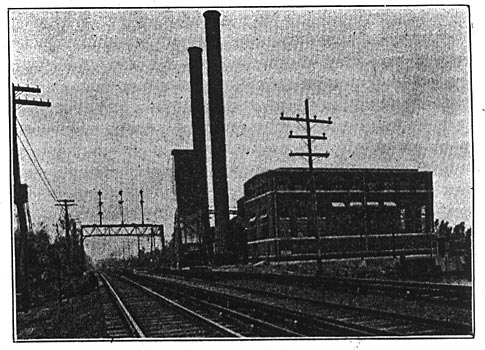
Fig. 1 shows the power house, which is situated at Big Timber Creek, just to the north of Westville, N. J., at a point 5.6 miles from the Camden Terminal, where there is an abundance of water for boiler feed and condensing purposes. As already intimated, this building, in all probability, was erected at a greater speed than any other power station hitherto built in the United States.
For the sake of brevity, the main portion of the electrical equipment of the power house may be listed as follows:
Three 2,000-kilowatt, 6,600-volt, 25-cycle, three-phase Curtis turbo-generators.
Two 75-kilowatt, 25-cycle, air-blast transformers.
Three blowers, each having capacity of 20,000 cubic feet per minute.
The switchboard consists of:
Three three-phase generator panels.
Two exciter panels.
Three blower motor panels.
One synchronizing equipment.
Three 33,000-volt transformer panels.
Two sets lightning arresters and switches.
Six static potential indicators.
Two 33,000-volt out-going line panels.
It will be seen from the above that the present normal capacity of the generating station is 6,000 kilowatts. Moreover, there is sufficient room provided in the layout of the building for an additional 2,000-kilowatt turbo-generator set, together with the necessary auxiliaries. The foundation for the extra turbine is already built. In addition to this provision for extra power one of the end walls of the station is of a temporary nature in order that increasing demands for power may be met with a minimum of expenditure in the future.
Among the auxiliaries the most important items are as follows:
1. Two exciter sets, consisting of horizontal Curtis steam turbines coupled to 75-kilowatt four-pole General Electric direct-current generators running at 2,400 revolutions per minute, and delivering 600 amperes each at 125 volts pressure. The turbines of these sets work non-condensing, as the exhaust is used for heating the feed water.
2. Three barometric condensers built by Williamson Brothers, in connection with Cramp & Co. of Philadelphia, who were also the sub-contractors for the circulating and air pumps. These condensers are capable of maintaining a vacuum of 28 inches and are designed to condense 60,000 pounds of steam per hour with circulating water at a temperature of 70 degrees F. The approximate ratio of condensing water to steam condensed is 75:1.
3. Three dry-air pumps built by I. P. Morris & Co. of sufficient capacity to fulfill the guarantees given with the condensers.
| |||
| Fig. 1. Power House at Westville, N. J., of West Jersey and Seashore Electric Railroad. |
4. Three centrifugal circulating pumps, built by the I. P. Morris Company and driven by Reeves engines. The piping for these engines is so arranged that the exhaust may be discharged to either the feed-water heater or to the third stage of the turbines, the latter arrangement only being used when the exhaust from the other auxiliaries exceeds that required for the feed-water heater.
5. Two Cochrane feed-water heaters. Each heater has a capacity for heating 135,000 pounds of water per hour from 70 degrees F. to 212 degrees F.
6. Two Worthington boiler-feed pumps.
7. Two Worthington make-up pumps.
8. Two Worthington step-bearing pumps.
9. Three Worthington step-bearing water return pumps.
10. One accumulator for the step bearings with a capacity of loo gallons of water at 800 pounds pressure per square inch. This accumulator was supplied by R. D. Wood & Co. of Philadelphia, Pa.
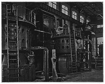
The area of the power house is 17,069 square feet, and the cubic contents amount to 829,113 cubic feet, thus giving 2.13 square feet arid 103.6 cubic feet per kilowatt as the unit output of the station, based on 8,000 kilowatts as the ultimate capacity of the present structure. The three turbines now erected are shown in Fig. 2.
Steam piping in the power house is laid out after an excellent design and allows ample operating space around all the machinery. W. K. Mitchell & Co. of Philadelphia, Pa., were the sub-contractors for this work together with the steam valves, etc., and Keasbey & Mattison furnished the pipe covering.
Twelve Stirling water-tube boilers are arranged in pairs in the boiler house, forming six batteries. Each boiler is rated at 358 horsepower, and is furnished with a superheater capable of delivering steam at 175 pounds pressure and at a temperature of 125 degrees F. in excess of that of saturated steam. The Stirling Boiler Company of Barberton, Ohio, was the sub-contractor for both the boilers and boiler settings.
Coal is dumped from the railway cars into the receiving hopper, over which the rails are laid. The receiving hopper has a slanting bottom to feed the coal by gravity through a valve which is only opened when the skip is in the correct position for loading. The loaded skip is raised by means of a hoisting engine till it reaches the level of the deflector, when it is automatically tipped into the crushing hopper, the smaller coal passing through the screen and the larger coal being broken in the crusher in transit. From this hopper the coal is fed into the gravity return car by means of the valve at the bottom, when it is conveyed by the automatic railway over the coal bunkers into which it is tipped. From those bunkers it is again fed to the coal cars on the tracks on the boiler-room floor.
The ashes are taken from the boiler house in cars and dumped into the receiving hopper, from where they are raised in a similar manner to the coal, but the deflector being thrown in the reverse direction from that shown in the illustration. The ashes are conveyed from the ash chute to the ash-storage bin, from whence they are convened by means of a chute to cars on the railway track.
SUB-STATIONS.
To reduce in potential the high-tension three-phase current and convert it to direct current at 650 volts eight sub-stations were distributed along the line. One is located in the power house at Westville. There are three terminal sub-stations situated respectively at South Camden, Clayville and Atlantic City, and four intermediate sub-stations, one at Glassboro, one at Newfield, one at Mizpah, and one at Reega.
Equipments in the several different sub-stations vary according to the requirements of the portion of the road they supply. The tables show the number and capacity of rotary converters installed in each sub-station and a list of the switchboard panels.
The rotary converters are all of standard General Electric design, and are capable of running at 150 per cent. full load for two hours with a temperature rise not exceeding 55 degrees. The transformers are all supplied with taps giving one-third and two-thirds of the working voltage to enable converters to be started from the alternating-current side. This method of starting needs no synchronizing, and should fhe direct-current polarity of the machine chance to come in the wrong direction it is readily changed by means of the field-reversing switch provided for this purpose. By this method any of the rotary converters can be started, run up to full speed, and be delivering power to the line within a minute.
| |||
| Fig. 2. Steam Turbinies in Westville Power House of West Jersey and Seashore Electric Railroad. |
Three air-cooled transformers are provided for operation in conjunction with each rotary, and these are located in each case with a view to the further extension of the sub-station, and as they are all of standard design it is not necessary to go into details regarding their construction.
| |||
| Fig. 3. Lighting-Arrester Room at Newfield Sub-Station. Views in Sub-Stations of the West Jersey and Seashore Electric Railroad. |
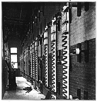
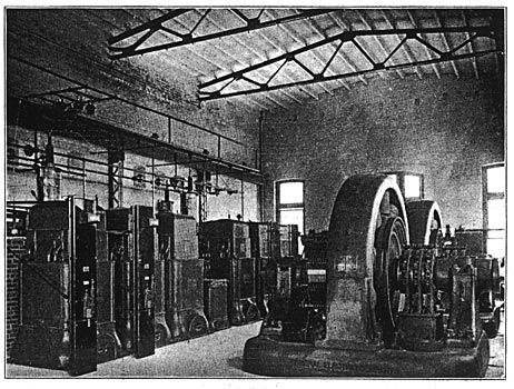
The disconnecting switches and lightning arresters in each sub-station are located in a separate room (Fig. 3). The high-tension circuits are of bare copper wires supported on insulators on a pipe framework, and each pole of the oil switches is enclosed in a separate brick compartment. In all cases the instruments and oil switches are of General Electric design. Fig. 4 shows the interior of the Atlantic City sub-station.
| |||
| Fig. 4. Interior of Sub-Station at Atlantic City. Views in Sub-Stations of the West Jersey and Seashore Electric Railroad. |
INSPECTION SHEDS.
Inspection sheds have been built at the three terminals. The largest one is on the dock at Camden, just back of the new passenger terminal. This is a three-track shed 221 feet long by 56 feet wide, accommodating nine cars, with room for office, storeroom and small machine shop at the end opposite to the entrance. All tracks have pits, provided with steam heating, electric lights and receptacles and compressed-air outlets for cleaning. The third rail is not carried into the shed, overhead trolley being used instead. The center track has overhead hand-operated crane, with runway extending into the machine shop. At Atlantic City the shed is of the same general arrangement, but smaller. The shed at Millville has one track and is of sufficient length for one car, with space to work around a truck when run out at one end.
HIGH-TENSION TRANSMISSION LINE.
The 33,000-volt high-tension transmission line is in duplicate throughout. It is Y-connected, with the neutral grounded, and consists of six No. 1 B. & S. hard-drawn solid-copper wires mounted on porcelain insulators. The poles are of chestnut, their height being 45 feet, with extra long poles where special conditions require. They are spaced 125 feet, but at street crossings the spacings are reduced to 100 feet. Head guys are used at distances of approximately one-quarter of a mile. There are two cross-arms, the top arm being 12 feet in length, carrying four insulators, while the lower arm, which is eight feet six inches, carries two insulators. The six wires form two inverted equilateral triangles, and the insulators on each triangle are 42 inches apart. The wires in each triangle are transposed by one complete spiral between each sub-station.
Cross-arms are bolted to the poles, and as an additional support they are stiffened with galvanized-iron braces. Locke insulators are used, made in three parts and designed to stand double the working pressure. Each petticoat was tested separately, the top section to 45,000 volts. In each case these tests lasted four minutes, and following this the assembled insulator was subjected to 85,000 volts for 10 minutes, and also a precipitation test was made at 52,500 volts. The insulators are mounted on iron pins.
A unique feature of the transmission line is the method of protection from lightning, which consists of a seven-strand galvanized-steel cable 5-16 inch in diameter strung for the entire length of the line on top of the transmission poles, four feet above the nearest active wire, and provided with ground connections at every fifth pole. This form of protection from lightning is believed to be an efficient supplementary adjunct to the arresters.
In all there is 71 miles of transmission line. This was erected at a speed of from one-half to two miles a day; the work including the digging of holes and pole erection, besides the stringing of six wires and tying them in position to their respective insulators.
THE THIRD RAIL.
To install the third rail for a double-track road of this length in the prescribed, time demanded a considerable amount of skill on the part of those organizing the work, and the fact that a large amount of steam traffic and double-tracking was going on at the same time materially added to the difficulties of the undertaking. The rails used for this purpose are of the Pennsylvania Railroad standard cross-section and composition; they are in lengths of 33 feet, weigh 100 pounds to the yard and have a conductivity about equal to that of a copper rod of 1,200,000 circular mils. This type of third rail was used in order that it might be interchangeable with the track rails.
The insulators are of reconstructed granite, and are held in position by a metal-centering cup which is secured to the long ties by means of a lag screw. The insulators are spaced about eight feet apart. The top of the third rail is 3 1/2 inches above the top of the track rails, and its gauge 26 inches distant from the gauge line of the adjacent track rail, these dimensions constituting the standard of the Pennsylvania Railroad and the Long Island Railroad, and also interchangeable with the Interborough Rapid Transit of New York city.
The approaches of the third, rail are made of cast iron. The third rail is bonded with concealed ribbon bonds with solid-copper terminals compresed into one-inch drilled holes in the rail. There are two bonds to a joint, and each has an area of 500,000 circular mils, giving a total area of copper per third-rail joint equal to 1,000,000 circular mils. The work of bonding the third rail was accomplished at the rate of 660 bonds a day.
| |||
| Fig. 5. Cattle Guards, Jumper Boxes and Third-Rail Covering at A Crossing on West Jersey and Seashore Electric Railroad. |
The third-rail jumpers are of especially neat design. They are used at all grade crossings and wherever continuous third rail is impracticable. The cable is drawn into a black bituminized fiber tube, which is laid in a solid concrete protection. Terra-cotta covers are employed to protect the cable terminals. Those for a single-cable juniper are of the round form and those for double cable of an elliptical shape. Fig. 5 shows the jumper boxes and third-rail covering at a crossing at Westville.
For protection, the company's right-of-way is fenced in, and at all crossings (as shown in Fig- 5) the fence turns in from the property line to meet Climax cattle-guards at the edge of the crossings. In this way the public is prevented from reaching the third rail.
At all stations and in the Atlantic City and Camden yards the third rail is protected by a wooden top and side guard. This consists of a two-inch plank carried on castings attached to the top of maple posts, which are secured to the third rail at intervals of about six feet. Opposite all platforms the rail is further protected by a plank fastened to the side of the rail.
At Atlantic City, where the tracks cross the Thoroughfare, a new drawbridge has been built. The third rails on this draw are connected to the third rails on the approaches by sliding contact shoes, so that when the draw is closed the rail is continuously connected. In addition to this two 1,000,000-circular-mil submarine cables are provided connecting the rails so that the opening of the draw does not interrupt the circuit. The submarine cables for the return circuit are bare.
TROLLEY LINE.
Trolley construction between Newfield and Millville and on the stretch of track between Haddon Avenue and South Gloucester is of the span type, with poles spaced at a distance of 100 feet, and where practicable the high-tension transmission poles have been used for supporting the span wires. Through Camden the greater part of the trolley construction is on tubular steel poles. The trolley is suspended 22 feet above the top of the track rails. The length of line between Newfield and Millville is approximately 10 miles. The trolley wire is of No. 0000 grooved section. The span wires are of standard galvanized steel 3/8 inch in diameter. The lightning arresters are installed at approximately 1,000 feet apart.
CARS.
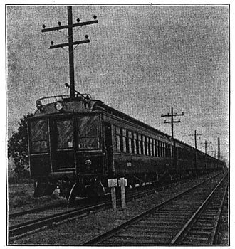
For initial service 62 passenger cars and six combination baggage and mail cars have been provided. All of the cars are motor cars, the motor and central equipment being the same on all. In preparing the design of these cars, the engineers of the railroad followed the general design of the standard Pennsylvania Railroad coaches, except that the height is less than the standard to decrease the weight, the shape of the roof is changed and the interior finish is of mahogany instead of oak. Fig. 6 shows a train of motor cars.
Fifty-eight passengers can be seated. Both ends of the cars are provided with vestibules. The cars are 55 feet 5 1/2 inches long over buffers and 46 feet six inches over body. The total weight of car, fully equipped on track, is 89,000 pounds. The combination baggage and mail cars are of the same general dimensions as the passenger cars.
All cars are provided with a 50-candlepower incandescent electric headlight and two electric markers or route lamps on the hood at each end. In the interior of the car there are five five-light clusters and in the saloon there is a single lamp. There are two lights in each vestibule.
Each car has two trolleys, each with a retriever, and on the roof between the trolley bases there is a box containing the lightning arrester, trolley cut-out switch and trolley fuse. The cars are heated by Gold cylindrical heaters, one being under each seat and a total of 28 heaters per car. There are two coils in each heater, thus providing three degrees of heat.
In the vestibule, at the saloon end of the car, on the motorman's side, there is a switchboard on which are mounted the headlight and air-compressor switches and fuses, the switch for cutting out the contact shoes when operating on trolley, the trolley cut-out switch and current limit relay. This switchboard is provided with double steel doors lined with asbestos and is accessible from the vestibule.
TRUCKS.
The motor and trailer trucks are of the M. C. B. double side-bar equalized type somewhat similar to those used on the cars of the Interborough Rapid Transit Company and the Long Island Railroad, but with greater wheel base. The general dimensions of the trucks are as follows:
|
BRAKES
The cars are equipped with hand brakes and with Westinghouse quick-service automatic air brakes, Schedule "AMT." This brake schedule includes the brake valve, brake cylinder, triple valve, feed valve for reducing main reservoir pressure to 70 pounds, the brake pipe for train line, switches, gauges, reservoirs, etc., together with what is known as the control line. This line extends through the train, and besides insuring uniform pump labor on all cars, provides, in connection with other apparatus, for the graduated release. The motorman is able to divide the process of release into as many steps as may be desired, securing the same flexibility as with straight air.
MOTOR AND CONTROL EQUIPMENT.
Electrical car equipments were furnished and installed by the General Electric Company. There are two G.E.-69 motors, which are 200-horsepower units, on each car, while the control system is of the Sprague-General Electric automatic multiple unit type. The controllers are so arranged that current .is cut off from the motors throughout the train and the brakes are applied automatically should the motorman release his hold of the controller handle.
For the sake of brevity, these equipments will not be described in detail, as they are of standard General Electric design. With the exception that each car is provided with a trolley and third-rail shoe, the control system is similar to that on the 24 equipments supplied to the Boston Elevated road some 18 months ago.
ORGANIZATION.
The conversion of the lines of the West Jersey and Seashore Railroad from steam to electric traction was carried out by the following organizations:
The construction of the terminals, inspection sheds, double-tracking, changes in existing tracks, grading, new bridges, changes in telegraph lines, and installation of a special telephone system, were carried out by the regular engineering and maintenance-of-way departments of the Pennsylvania Railroad Company.
The installation of the interlocking plants and automatic block signaling was carried out by the Union Switch and Signal Company in accordance with plans of the signal department of the Pennsylvania Railroad Company.
The new cars and trucks required for the electric service were designed by the motive-power department of the Pennsylvania Railroad Company.
| |||
| Fig 6. Motor-Car Train on West Jersey and Seashore Electric Railroad. |
The entire contract for the electrical equipment, including the construction of the power house, sub-stations and the electrical equipment on the cars, was awarded to the General Electric Company, and in accordance with the plans and under the supervision of Mr. George Gibbs, chief engineer of electric traction, in consultation with the officers of the railroad company. Stern & Silverman of Philadelphia were appointed by the General Electric Company as their general sub-contractors, and the Scofield Company, also of Philadelphia, acted as general engineer for the power house and sub-contractor for the piling and foundations.
The whole of the electrical work was under the personal supervision of Mr. W. B. Potter, engineer, railway engineering department, General Electric Company, directly assisted by Mr. J. Elliot Hewes, Mr. C. E. Eveleth and Mr. W. H. Clapp.
