[Trade Journal]
Publication: Western Electrician
Chicago, IL, United States
vol. 40, no. 18, p. 383, col. 1-3
The Recent Italian High-tension
Experiments.
BY FRANK C. PERKINS.
Some experiments of unusual importance were recently made by Messrs. Pirelli, the Italian electrical engineers, with pressures ranging from 160,000 volts to 320,000 volts.
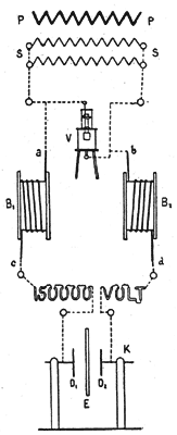
In these experiments a 200-horsepower transformer was utilized, arranged as shown in the accompanying diagram, Fig. 1. The primary was wound for 160 volts and fed directly from the city service main. There are two similar groups of coils in the secondary (S), arranged to be connected in parallel or in series, and thereby obtaining potentials of 160,000 volts or 320,000 volts, as desired.
 |
| Fig. 1. Connections for Italian High-Tension Experiments. |
A potential of 200,000 volts was measured directly by means of an electric static voltmeter (V), connected as shown in Fig. 1, while for higher potentials the voltmeter was connected to one of the terminals of the transformer as well as to the middle point of it, thereby measuring half of the total voltage at the terminals of the secondary.
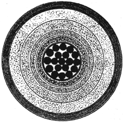
The Italian engineers arranged two drums (B1) and (B2), each of which was wound with a length of high-tension cable of 120 meters. A section of this cable, full size, is given in Fig. 4. Various layers of different dielectrics are used for insulation, partly vulcanized rubber and partly paper, the whole sheathed in lead.
To one of the terminals of the secondary of the transformer, which was connected in parallel, as noted in Fig. 1, one of the ends of each of these two coils (a) (b) was connected, while the other two ends (c) and (d) were connected to a number of vacuum tubes in series, forming the words, "150,000 volt."
In series with the vacuum tubes a small condenser was connected, formed by a disk of ebonite (E) separating two movable copper disks (D1) and (D2), the distance betwen the armatures being regulated from 15 to 20 centimeters in order to adjust the current in the tubes and obtain good brilliancy. As the impressed voltage was too high for the tubes, the condenser became necessary, and the cables formed a part of an electric line working at a pressure of 150,000 volts steadily.
 |
| Fig. 2. High-Tension Cable Arranged for Breakdown Test. |
A number of pieces of this cable about 20 feet in length were tested to the point of breakdown, the ends being especially prepared to obviate surface discharges, as shown in the accompanying drawing, Fig. 2. By means of a suitable resistance put in the primary the tension could be gradually increased until a pressure of from 200,000 to 210,000 volts was applied between the lead sheathing and the conductor, when the cable broke down. The diameter of the conductor was 18 millimeters and the total diameter was 48 millimeters over the insulation, making a thickness of 15 millimeters for the dielectric, the experiment showing a very high rigidity. Referring to Fig. 2, (C) is the conductor, (I) and (R) insulation and covering, and (P) a porcelain insulator. The insulation (R) is a resinous material, the lead covering (T) of the cable entering the lower block, of this insulating material at (B). This special precaution in the insulation in the end of the cable was necessary in order to obviate surface discharges in these high-tension experiments. The conductor is absolutely cylindrical, the copper strands being sheathed with lead.
 |
| Fig. 3. Connections for Rotary Spark-Jet Experiment. |
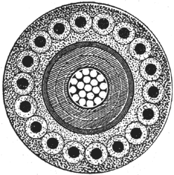
Fig. 5 shows a section of the cable tested by Messrs. Pirelli which was recently laid across Lake Garda. This cable was laid for the transmission of power at a pressure of 13,000 volts from Ponalle to Rovereto, about 6,000 kilowatts being employed, three-phase currents being utilized. The section (Fig. 5) is full size, the stranded conductor being 75 square millimeters, sheathed in lead tubing, this being insulated by a number of layers of vulcanized india rubber to a thickness of 5.5 millimeters, outside of which is a coating of gutta-percha of 1.2 millimeters, to exclude any water. There is an outer covering provided with an armor of 18 steel wires, each having a diameter of three millimeters. Each of these steel wires was wrapped with tarred hemp in order to avoid the effect of self-induction.
 |
| Fig. 4. Full-Size Section of Cable Worked at 150,000 Volts. |
This cable was tested between the conductor and sheathing up to 100,000 volts, and it is stated that fierce sparks were noted between the conductor and the sheathing running along the surface of the dielectric, but it is maintained that the cable withstood the pressure satisfactorily, although it was not possible, on account of this sparking, to increase the voltage above that amount.
 |
| Fig. 5. Full-Size Section of High-Tension Sub-Aqueous Cable. |
The accompanying drawing (Fig. 6) shows the large porcelain insulators, made by Richard Dinori [sic] Ginori, which carried the aerial two-wire line for these experiments, designed for lines of 60,000 volts and tested up to 2 1/2 times this pressure. This insulator, it will be noted, is 400 millimeters high and 320 millimeters in diameter. The wires were spaced 1.6 meters apart and consisted of copper strand of different diameters in order to show the difference of brush discharge with varying thicknesses of conductor.
It is stated that the smallest wire showed a brush discharge at 50,000 volts, this conductor having a cross-section of 20 square millimeters, while the largest wire showed a brush discharge only when the pressure reached 100,000 volts, the diameter of this conductor being 100 square millimeters. When the pressure was increased to 150,000 volts and up to 280,000 volts there was a bright brush discharge and a considerable hiss on the line. Sparks could be obtained from any insulated metallic mass on account of the electrostatic field being so intense, and vacuum glass tubes were lit up spontaneously. The experiment was stopped at 290,000 volts on account of the burning of the wooden supports, due to an arc from one of the insulators.
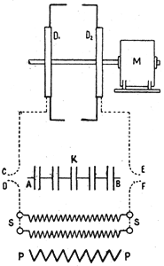
Fig. 3 is a diagram showing the electrical connection of the rotary spark-jet experiment made by Messrs. Pirelli, which is of great interest. The two ebonite disks (D1) and (D2) were of 25 centimeters radius and placed 250 millimeters apart on the shaft of a three-phase motor (M). The tension of the transformer secondary (S) was lowered to about 90,000 volts and arranged to charge a battery of condensers.
The disks above referred to were arranged with two bronze rings on the outer edge, to which were screwed two iron wires, the ends of which were 10 centimeters apart and 50 centimeters from the shaft of the motor, which operated' at a speed of 1,200 revolutions per minute. These rings were connected to the condensers, and the speed of the spark jet was 60 meters per second, with the motor operating at the above rate of speed.
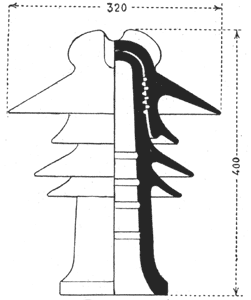 |
| Fig 6. Insulator for 60,000-Volt Line. |
It is stated that there was a brilliant circle of sparks observed which appeared to turn opposite to that of the motor rotation and quite as slowly, the speed being the slip of the motor.
These high-tension experiments were most interesting and instructive, and the construction of the high-tension voltmeter is of more than passing interest. This 200,000-volt electrostatic instrument was designed to measure the attractive force exerted by the lower fixed plate, which was connected to one of the transformer terminals (S), Fig. 1, on a movable plate connected to the other terminal, paraffine oil being employed for filling the apparatus. The lower plate is 280 millimeters from the upper plate, the latter measuring 50 millimeters in diameter. Mr. Gona, the engineer, says that the attractive force exerted on the upper plate is 23 grammes with a tension of 200,000 volts, and this electrostatic attraction is considerable when it is noted that the small plate has an area of only 20 square centimeters.
