[Trade Journal]
Publication: Western Electrician
Chicago, IL, United States
vol. 40, no. 25, p. 550-551, col. 3,1-3
Electrification of West Shore Railroad
Between Utica and Syracuse.
The section of the West Shore Railroad between Utica and Syracuse; N. Y., which has been equipped for electrical operation, was officially opened on June 15th. The occasion was fittingly celebrated, Mr. C. Loomis Allen, vice-president and general manager of the Oneida Railway Company, being in charge of the ceremonies. The work of electrification has been carried out by the Oneida Railway Company, a corporation identified with the so-called Andrews-Stanley syndicate, which syndicate, in conjunction with the Vanderbilt New York Central interests, owns several electric-railway properties in New York state.
The Qneida Railway Company entered into a contract with the New York Central Company under which the former agreed to lease the tracks of the West Shore Railroad between Utica and Syracuse, equip them for electric operation and conduct the passenger business between these two points. The New York Central on its part consented to abandon the West Shore local trains on these tracks but reserved, the right to continue its through steam trains and to haul freight over the electrified section by steam locomotives. Among the towns traversed are Oneida, Vernon and Canastota. The distance between Utica and Syracuse is a little over 44 miles, but under the West Shore schedule extremely scanty passenger transportation facilities were provided.
It is proposed to give three classes of service over the West Shore tracks between Syracuse and Utica fast limited electric cars or trains which will run hourly between the two cities and will make two stops only, completing the run in one hour and 28 minutes; local trains or cars; and the steam service.
To provide for passing the fast-moving units around the slower trains a third track has been laid between Clark's Mills and Vernon, a distance of 8 1/2 miles. In addition, between Oneida and Canastota, a distance of about 5 1/2 miles, a fourth track has been laid to pass the electric units around the freight trains that may be held up in the yards or at watering statiens. The outside tracks will be used for the local trains.
POWER TRANSMISSION LINES.
Power for the operation of the line is purchased from the Hudson River Electric Power Company, which owns the hydraulic power plants at Spiers Falls and Mechanicsville. This company is now extending its transmission line from its water-power plants to Utica, and expects soon to be able to deliver electric power to those points at 60,000 volts. A temporary steam plant is now used.
The contract of the power company provides that it shall deliver power to the transmission circuit of the railway com'pany, which commences at the Clark's Mills sub-station, which is that nearest Utica. The power company's transmission line for this distance of 4 1/2 miles is constructed on a private right-of-way adjoining the West Shore tracks and is carried on two-circuit steel towers, spaced approximately 550 feet apart. At Clark's Mills the current is taken by the Oneida Railway Company and is conducted to the three other sub-stations over its own transmission line, which is also built on the private right-of-way of the West Shore Railroad. For serving the entire section between Utica and Syracuse, about 44 miles, there are four sub-stations.
The transmission towers used on the Oneida Company's transmission line differ frorn those employed on the power company's line. They consist essentially of a square latticed structure composed of four angles, 3 by 3 by 5/16 inch carried down five feet to reinforced concrete footings under each pier, measuring 5 feet by 3 feet by 10 inches. The distance between towers is 480 feet.
The insulators are of porcelain, supplied by R. Thomas Sons & Co. of Lisbon, Ohio, and are placed at the corners of a seven-foot triangle. They are carried on malleable iron pins 18 inches high, which are designed to withstand a strain of 2,000 pounds applied in any direction at the top of the insulator.
A No. 0 seven-strand hard-drawn copper cable is used for each conductor. Where heavy strains occur, necessitating a double cross-arm, the cable, instead of resting on insulators, is attached to an equalizing saddle to distribute the load equally over several insulators. The use of lightning arresters is confined to the sub-stations themselves.
SUB-STATIONS.
The four sub-stations are of similar design. They are of brick with litholite trimmings, concrete roof and concrete floors. They are divided into two main compartments at the rear the high-tension room and in front the converter room. This being one of the first 60,000-volt installations in this section of the country, extreme care has been taken to give the necessary clearances on the high-tension side. The high-tension line enters the under side of a protecting hood at the rear of the building and thence passing through circular openings three feet in diameter in the wall of the building to the disconnecting switches and onto the bus compartments.
The high-tension room is two stories in height, the floor being carried only to the face of the barrier walls, which run three feet apart and three feet in depth, up and down the rear wall, this provides a number of cells or compartments open from top to bottom, which are used for the installation of the lightning arresters and bus-bars.
Against the forward wall on the second floor of this high-tension room are built similar barriers forming cells, in which are installed the high-tension oil switches. These switches are General Electric type H, motor operated. On the first floor of this high-tension room and immediately under the oil-switch compartment and running transversely through these barrier walls supporting the oil switches there are three compartments, three feet square, one above the other, and extending the length of the room. These are the bus compartments proper and carry the high-tension line through the station. It is from these buses that taps are made and earried up to the oil switches.
In the converter, room are the transformers, rotaries and switchboard. All of the high-tension wires as far as the transformer terminals are of bare copper wire. In the converter room are two units consisting of one 330-kilowatt 60,000:370-volt oil-cooled transformer, Y-connected on the primary side and delta connected on the secondary side, and one 300-kilowatt 370-volt alternating-current and 600-volt direct-current rotary converter. Between the transformer and the rotary stands the reactance which is used for starting the rotary converters. This is the General Electric Company's latest method of starting rotary converters without synchronizing.
| |||
| Map of "Electrified" West Shore Railroad Between Utica and Syracuse, N. Y. |
The direct-current feeder panels are connected to the third rail at the station by means of'rubber and lead-covered cable, each track being independently fed each way from the sub-station that is, on a two-track section there would be four, feeder panels. Auxiliary feeders will not be necessary for the service contemplated. A storage battery is located in the subway and is used in operating the oil switches.
THIRD RAIL.
The third rail is of the bull-headed or double-headed type, of the same section as that adopted in the New York city zone of the New York Central Railroad, and is adapted for under-running contact. It weighs 70 pounds per yard and was supplied by the Lackawanna Steel Company. The conductivity of the rail is equivalent to 1,023,000 circular mils of copper. This conductivity is sufficiently large so that no auxiliary direct-current feeders are required.
The clearance on the West Shore will permit the passage of all of the cars belongng to the New York Central system and all foreign cars except a very limited type of coal cars with low truss rods. Electric locomotives and motor cars designed for use on the Central tracks can also be run over the West Shore tracks without changing the position of the third-rail shoe. The third rail is normally located between the tracks on tangents and on the high side of the track on curves.
INSULATORS.
The insulators used for holding the third rail in the brackets were supplied by the Ohio Brass Company and are of semi-porcelain. Two sizes are used, one for holding the rail at the inclines where a shallower insulating block is required, the other for supporting the rail at other points. The insulators are required to pass rigid tests. They must be capable of withstanding a tensile stress of not less than 1,400 pounds without showing any indications of failure.
A great deal of study was put upon the proper material for the insulating block. To secure the necessary combination of mechanical strength and electrical insulation the manufacturers made an extended study of combinations of different clay and porcelain mixtures as well as various methods of drying and burning the pieces. The resultant was a product termed "semi-porcelain."
In laying the third rail a space of about one-quarter inch is left at each joint for expansion and contraction.
Two types of protective covering are used, as on the New York Central, viz., a three-part wooden covering which was originally adopted and a single-piece fiber covering which was manufactured by the Indurated Fiber Company and is considered preferable. The wooden sheathing is of long-leaf yellow pine in three parts, top and two bases. It is not treated with any preservative except a coat of ordinary paint. The indurated fiber sheathing is molded for straight track in sections 43 1/2 inches long. The joints on straight track are covered by a 3 1/2-inch lap joint of the same material. At the bonds a wider section of' covering is used.
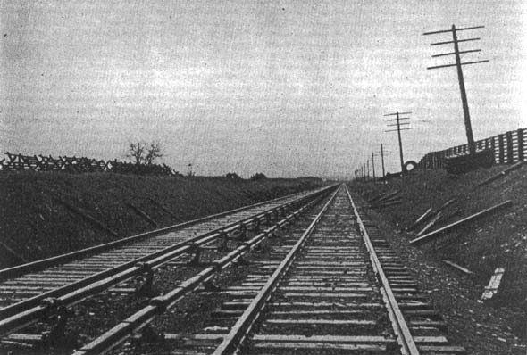
| |||
| View on "Electrified" West Shore Railroad Showing Third-Rail Construction. |
The majority of the bonds on the third rail are the John A. Roebling's Sons Company's ribbon bond. These bonds are 15 inches in length over all and are soldered to the rail, one on each side of the upper head. and have a very large contact surface per terminal. There have also been installed on. a portion of this line about 3,000 Ohio Brass Company's ribbon soldered bonds and about 7,000 American Steel and Wire Company's twin terminal bonds. These bonds are of 500,000-circular-mil capacity each, and are installed two per. joint on the upper head of the third rail.
The running rail is bonded with the Ohio Brass Company's 11-inch compressed terminal bond, placed under the fish-plate. There is one of these at each joint, and each bond is of No. 0000 capacity. The track is cross-bonded only at special work. Both rails are available for use for the return circuit.
The connection between the direct-current bus-bars in the various sul-stations and the third-rail system is made through several cables of 1,000,000-circular-mil capacity, carried in iron ducts three inches in diameter. The cable is insulated with 3/32-inch rubber and is lead-encased. The end of this duct at the track is brought up to two inches below the top of the track rail, or 2 1/2 inches above the surface of the tie.
CARS.
As the cars are to operate over the city system in both Utica and Syracuse, a different type was adopted than if they were to use the West Shore tracks exclusively. They are about 48 feet by eight feet four inches over all. The interiors are of inlaid mahogany. The floor is covered with interlocking elastic tile. The cars are equipped with 24 reversible and two stationary plush seats with high backs and head rolls. Each car is also fitted with a toilet.
The truck used is the Brill No. 37-E-2, with a wheel base of six feet six inches. The wheel tread is four inches wide and the depth of the flange is one inch, to allow the cars to operate over the city systems in Utica and Syracuse. Each car is equipped with four GE-73 motors with Sprague-General Electric multiple-unit control. Westinghouse automatic air brakes with graduated release and Peter Smith hot-water heaters are used.
