[Trade Journal]
Publication: Western Electrician
Chicago, IL, United States
vol. 41, no. 1, p. 2-3, col. 1-3,1-2
Some Power Transmission Economics.¹
BY FRANK G. BAUM.
In designing power transmission systems it is always well to bear in mind that the ultimate development of the art and of the country has not yet been reached. The wise manager or engineer builds to meet existing conditions, looking into the future as far as he can. It may not be as difficult to determine the proper power station and line to build when unlimited capital and ideal power conditions exist as when there is restricted capital, limited revenue and' low-priced power at the consumer's end.
 |
| Fig. 1. Profile of Mountain Pole Line. |
To illustrate the necessity of doing things in inexpensive ways in the early development of an art, a business or a country, some examples are given of the work done on the system of the California Gas and Electric Corporation. Along some of the lines where the load is small, one wire only is run to the sub-station, an inexpensive building, and one transformer, with ground return, is installed. One-phase motors are used. For larger stations, sometimes up to 500 kilowatts, two wires are run to the sub-station, and by using ground return on the primary and open delta on the secondary, three-phase motors are operated. Loads as large as 1,500 kilowatts have been carried to a distance of 100 miles on two transformers Y-connected on the primary, with grounded neutral, and open delta on the secondary. Neither the power consumer nor the power-house operator has noted anything unusual.
 |
| Fig. 2. Standard Types of Pole Structures Used in California. |
For larger sub-stations a single three-phase transmission line supplies the load, even where the length is 50 miles or more. The consumer cannot afford to pay for a duplicate line when the output per year of the factory is practically unaffected by interruptions. Interruptions amounting to one hour per month would be one-seventh of one per cent. of the total time, and the power company that has an average of an hour's interruption per month is certainly giving very bad service. It is evident that the construction of a duplicate pole-line for such service is entirely unwarranted.
As to the construction of pole lines, it has been found that in some parts of the West where cedar poles may be purchased at a low price, this class of pole lines is still the most economical, and everyone must admit that this type of construction has proved remarkably effective. Of course under certain conditions tower lines only would be considered, but two wooden pole lines entering a city by two different routes will give greater reliability than any two-circuit tower line that can be built. The cost of a two-circuit tower line would be as great as that of two pole lines. A line using tower construction requires a private right-of-way, and in a new country it may not be possible to pay from the earnings the interest on the increased cost of the right-of-way as well as on the tower construction. The engineer, of course, always prefers the best construction, but he must consider the net revenue to be derived from an enterprise in a given number of years. In mountain sections the economies of line construction lie in the use of the hills for the structures and in using long spans. In some cases the amount saved in clearing, in poles, insulators and labor will amount to 50 per cent.
 |
| Fig. 3. Pole-Top Extension. |
Fig. 1 shows a profile of a line recently constructed, the middle section of which consists of a series of spans varying in length from 700 to 2,700 feet. It will be seen that by taking advantage of the hills to form the greater part of the height of the structure great economy results. A span of 3,000 feet, with an allowable sag of 300 feet, would, if on the level, require towers over 300 feet high, while in this line on similar spans simple wooden pole structures 30 feet high are all that is necessary. The profile of a line of this kind is first determined, and the span-length and structures designed so that the wires clear the ground sufficiently. This gives an economical and satisfactory line.
 |
| Fig. 4. Three-Pole Grouping of Oil Switches. |
On long spans the wires are spread at the structures as shown. In addition the top or middle wire is given 10 to 40 feet less sag (depending on the span) than any of the others. One of the outside wires is also given 5 to 20 feet less sag than the other. In this way there is obtained a vertical separation at the middle of the span; and 10 feet of vertical separation is better than 20 feet of horizontal, because the wires then cannot come together, even when acted upon by gusts of wind having a tendency to lift the wires. Spans greater than 2,000 feet are not installed except in certain cases where it can scarcely be avoided. Spans of-600 to 1,300 feet give the best line.
Fig, 2 shows standard types of pole structures used on some of the mountain lines recently constructed in California. Structures of this kind are also sometimes used for river crossings where the cost of steel towers is prohibitive, or the time too short to install them. These are sometimes over 100 feet high.
Referring to old lines which were constructed 10 or even five years ago, nearly all the lines were built with 40 poles to the mile, using 35-foot poles. Now the tendency is to use longer spans on account of the lower cost and the reduced number of insulators or weak points in the line. Some of these old lines have later to be reconstructed for a higher voltage, and in order to obtain a reasonably good line and also to reduce the cost for insulators and future line maintenance it is advisable in reconstructing to reduce the number of poles. To do this the supporting points of the wires must be raised higher above the ground. In order to accomplish the result of reinsulating and reconstructing several hundred miles of line (which would have kept all the insulator factories busy for two years furnishing insulators for the old type of construction), the pole-top extension shown in Fig. 3 was used. This has proved effective. By using this pole-top extension, every other pole is taken out, with a saving of $9 per pole for new insulators, with the additional salvage of the old poles, arms, pins and insulators. Where sufficient height can be obtained by putting the arm below the top of the pole this construction may be simplified in the fastening of the arm and pipe to the pole.
Another important adjunct of the transmission line is the switches, oil and disconnecting. It will be found that the same arguments regarding economical line construction apply to switches. In selecting switches and structures for high-tension lines it is well to bear in mind that the ultimate development has not yet been reached. In solving our switch problem this was kept in mind at all times.
 |
| Fig. 5 Outdoor Two-Break Air Switch. |
The first high-tension oil switches were made as inexpensive and as simple as possible. These operated so satisfactorily that we became convinced of the success of the type and soon changed to a more substantial form. They are generally installed for hand operation. Although we have more than 100 of these switches on our lines, and nearly 1,000 miles at 60,000 volts all tied together, and over 50,000 kilowatts in generators operating on the lines at all times, the switches, although cheaply constructed, have given excellent results. All line switching is done on these high-tension switches, and the plants and lines are separated thereby in case of trouble. The stations are synchronized at sub-stations, which are 100 to 150 miles from any power station.
| |||
| Fig 6. Outdoor Switch. |
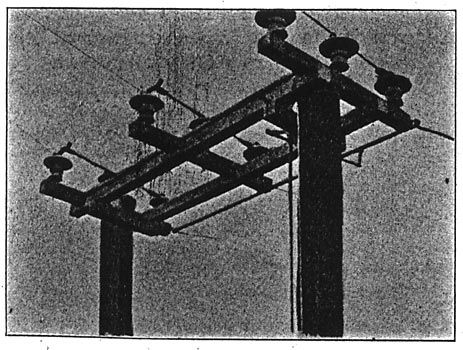
We have now adopted two-break switches for the ordinary station and four-breaks in each tank for the heavy service. These switches are grouped in three-pole arrangement as shown in Fig. 4.
For small sub-stations and for line-sectionalizing switches and for disconnecting from bus-bars, switches of the type shown in Figs. 5 to 8 are used. In handling the high-tension lines these switches are used as much as the oil switches.
 |
| Fig 7. Outdoor Switch and Fuse for Small Sub-Stations. |
The California Gas and Electric Corporation's high-tension lines are also. practically distributing lines, as loads are taken off at a great many points. We have more than loo sub-stations on our lines. Such a system is, of course, much more difficult to operate than a straight away line with a power station at. one end and a load at the other.
On the hydraulic construction and also on the power-house and sub-station installation and construction the engineer is required to devise something that will pay the largest net income in a given number of years.
 |
| Fig. 8. Side View of Oil Switch in Compartment, Showing Disconnecting Switches. |
I have given these examples of line and switch construction to show that the best solution of a problem may be one which accomplishes the purpose satisfactorily with the least amount of money on account of the changes in design which become apparent as our experience is broadened and as the industry develops. That there will be further advances is certain, but as far as high-tension work is concerned, little of the present apparatus transformers, insulators, switches need be thrown away; for should the line voltage be forced up, the present apparatus may be used on the lower voltage lines. And, too, the high-tension transformer is so flexible in its operating voltage connections that use can always be found for it. It is very probable that in time higher voltage trunk lines will be built which will feed into the present lower pressure (60,000 volts) lines at various points, using the present 60,000-volt lines for the primary distribution, stepping down to about 11,000 for the regular factory distribution. An example of work of this kind is shown by our system. A great many miles of comparatively low-tension lines 10,000 to 23,000have been changed to higher voltage, but all the old line material, switches, insulators, transformers, etc., have been again utilized.
The saving in conducting capacity and the improvement in the service and the salvage have well paid for all the changes. No doubt a part of the future work of the electrical engineer will be to redesign and reconstruct the high-tension systems for the economies to be gained. The ease by which the change to the higher voltage may be made as necessity arises is encouraging alike to the transmission engineer and to the investor.
1. Abstract of a paper read at the convention of the American Institute of Electrical Engineers, Niagara Falls, N. Y., ]June 26, 1907.
