[Trade Journal]
Publication: Western Electrician
Chicago, IL, United States
vol. 41, no. 6, p. 103, col. 2-3
A New Type of Insulator for High-tension
Transmission Lines.¹
By E. M. HEWLETT.
The transmission of large amounts of power over long distances has reached such proportions that the voltage necessary to transmit this energy makes the problem of line insulation difficult. The so-called "pin" type of insulator has been enlarged to meet the greater demands until it has approached, if not already passed, the limits of good construction. Mr. Buck has given this matter a great deal of study in his high-potential transmission work, and, being dissatisfied with the mechanical features of a pin insulator, has devised a method of line construction involving the use of "suspension" and "strain" insulators. The suspension insulators support the line from above, hanging vertically beneath the cross-arm (or other point of suspension). The strain insulators are used at turns and at intervals of, say, every mile, to support and' "anchor" the line, also as pull-off insulators on curves and to dead-end lines
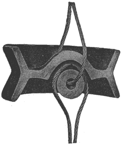 |
| Fig. 1. Tie Wires Arranged to Exert A Compression Strain on Insulator. |
It is intended in this paper to describe a porcelain insulator which the writer has designed to carry out this method of supporting of high-potential transmission lines.
Each insulator unit is a flanged or petticoated disk with an enlarged central portion having two interlinked semi-circular holes. It is called a "link insulator" because it is used to insulate the inter-linked tie-wires. The holes in the insulator are so arranged that the tie-wires which pass through them exert a compression strain on the porcelain (Fig. 1). Should the insulator break, the loops of the tie-wires wilt still be intermeshed (Fig. 2), and as the disks are used in series, with a factor of safety, the remaining disks will prevent a ground being formed until the break can be repaired.
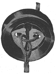 |
| Fig. 2. Loop of Tie Wires Intermeshed in A Broken Insulator. |
The link insulator for suspension (shown in Fig. 3) is a petticoated disk, while the strain insulator (Fig. 4) is a disk with a grooved flange. The mechanical and electrical features of the two forms of insulator are essentially the same. The petticoats and flanges are so arranged that one side of the insulator is always protected from rain.
A diameter of 10 inches for both types of insulators has been found by experiment to be most convenient, and such insulators are suitable for a working voltage of 23,000 volts per disk. For higher potentials the disks are placed in series; for instance, four 10-inch disks would be suitable for a 100,000-volt line. As the separate disks arc over wet at approximately 65,000 volts, the rated voltage of 25,000 volts is within safe limits. The 10-inch disks were tested and did not fail with a load of three tons.
 |
| Fig. 3. Link Insulator for Suspension. |
The insulators described above being made of one piece of porcelain, no cemented fittings or sections are necessary. They are not affected by extreme heat or cold, having stood the test of a severe winter. Tests prove that insulators with sheltered surfaces stand a much higher rain test than a much larger insulator which has no dry surface, as, for example, a flat disk without the flange or petticoat.
 |
| Fig. 4. Strain Insulator. |
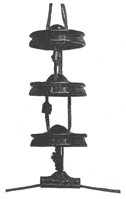
Fig, 5 shows a possible method of line support, using 10 towers per mile, in which the line is anchored at the end of each mile and at curves and suspended at intermediate towers. From the cut it will be noted that the conductor is looped around the strain links at the anchorage towers. The use of this type of insulator does away with torsional strain on the cross-arms, giving, it a decided advantage over the pin insulator. It is obvious that the link insulator is adaptable to a great variety of conditions.
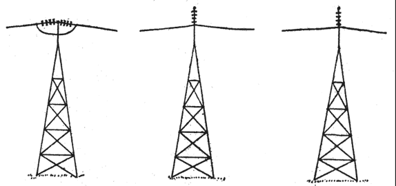 |
| Fig. 5. Method of Line Support Using Link Insulators. |
Fittings have been designed for use with these insulators to fit the conditions thus far presented, but each case should be considered as it comes up and such fittings designed as are necessary.
1. A paper read before the American Institute of Electrical Engineers at the Niagara Falls convention, June 26, 1906. Mr. Hewlett is an engineer of the General Electric Company.
