[Trade Journal]
Publication: Western Electrician
Chicago, IL, United States
vol. 41, no. 13, p. 236-237, col. 1-3
Electric Power Transmission.
BY CHAS. F. SCOTT,
Consulting engineer, Westinghouse Electric and Manufacturing Company.
TWENTY years is in most things a short interval, but in electric transmission of power it is an epoch.
The long-distance transmission of power, as commonly practiced today, was unknown twenty years ago. Some of its fundamental elements had not been discovered, and apparatus and methods which have been in common use for many years were yet to be invented and deevloped [sic] developed.
 |
| Chas. F. Scott. |
Practically all transmission today is by the alternating-current three-phase system. Twenty years ago the first alternating-current central station in this country had been in operation but a few months. The introduction of the alternating current was encountering the most strenuous opposition, by technical argument, by commercial antagonism and by attempted legal prohibition. There was no commercial alternating-current motor. It was not until May, 1888, that the Tesla patents on polyphase apparatus and transmission were issued and published. Transformers rarely exceeded two kilowatts in capacity and 1,000 volts in pressure. Insulators and lightning arresters had hardly become clearly differentiated from their telegraphic predecessors, from which they were evolved. Even the direct-current stationary motor was a commercial novelty, and all the electric railway systems in the country aggregated a length of track which could be traversed at present speeds in less than an hour.
| |||
| This Curious Illustration is Reproduced From the Western Electrician of June 23, 1888. the Text Very Briefly Explains That the Power Was Transmitted Four Miles, With 25 Per Cent. Loss in Transmission, to Operate A Motor for Driving A Stamp Mill in Idaho. An Early Power Transmission. |
BEGINNING OF THE NIAGARA DEVELOPMENT.
It is less than twenty years ago that an international technical commission was formed to determine the methods to be adopted by the Niagara Falls Power Company. It was not until 1893, during the World's Fair at Chicago, that final action was taken 'against the sentiment in favor of direct current by the formal decision to use polyphase alternating current.
At that time commercial frequencies were shifting from 133 cycles to 60 cycles. It was necessary to determine the frequency for the Niagara circuits. It was believed that much of the power would pass through large induction and synchronous motors, or synchronous converters, although such apparatus was more apt to be found in experimental testing rooms or in exhibits than in service. There was very little experience upon which to base the bold recommendation of a low frequency for so large an undertaking. The turbine speed had been fixed at 250 revolutions per minute. The power company's advisers proposed that the generator have eight field poles, giving 16 2-3 cycles (2,000 alternations); the Westinghouse Company recommended 16 poles and 33 1/3 cycles (4,000 alternations). The only possible intermediate course was finally chosen 12 poles and 23 cycles (3,000 alternations).
POMONA AND TELLURIDE PLANTS.
In 1892 the first 10,000-volt transmission plant in this country began operation in Southern California, transmitting single-phase current from San Antonio Canon for lighting Pomona and San Bernardino, approximately 14 and 28 miles. There were two banks of transformers, raising the pressure from 1,000 to 10,000 volts. In each bank were 20 six-kilowatt transformers, with primary 1,000-volt windings in multiple and secondary windings (each transformer giving 500 volts) in series. The transformers were oil-insulated, and the cast-iron cases were provided with ribs to increase the cooling surface. The transformers were connected to the line through simple disconnecting switches. The line consisted of No. 7 hard-drawn copper wire supported on specially designed glass insulators which were then considered of quite formidable size. At each sub-station there was a bank of transformers duplicate of those in the power house. There were no lightning arresters nor was there lightning. The system was about as simple as a typical diagram of a transmission circuit with raising and lowering transformers.
The Telluride single-phase synchronous motor plant was started in 1890. A 100-horsepower motor was operated at 3,000 volts at a distance of several miles. The Redlands plant in southern California, the first 10,000-volt three-phase transmission system in this country, was started about the beginning of 1894.
THEN AND NOW.
One may look through several volumes of the Transactions of the American Institute of Electrical Engineers in the early '90's and find scarcely a paper on transmission subjects; now the work of the transmission committee is one of the leading features of the Institute publications.
At the opening of the International Electrical Congress held at Chicago in 1893, it was found that there were no papers on power transmission among the considerable number which were on the programme. Dr. Louis Duncan came to the writer and asked that he prepare something to help start a proposed discussion on the subject. The outcome was an introductory paper, dealing particularly with the induction motor, by Dr. Duncan, and a description of the Westinghouse exhibit of polyphase apparatus in operation at the World's Fair, by the writer. These papers were followed by an animated discussion, which dealt with general principles rather than particular apparatus or methods. At the similar congress in St. Louis in 1904 there were many papers in the section on Power Transmission, most of them dealing with the results of experience and details of construction and operation.
| |||
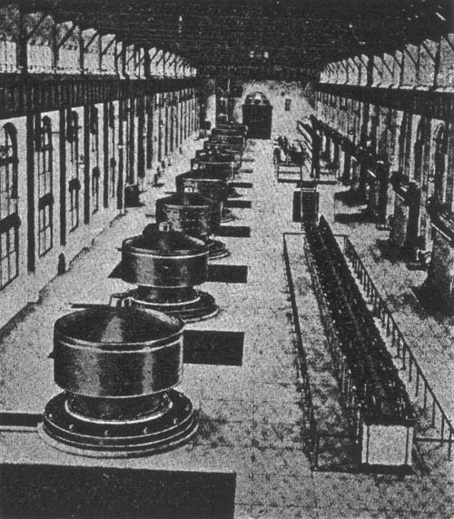
| Interior of A Niagara Falls Power House, Showing 10 Vertical 5,000-Horsepower Generators. |
Such, then, was the early condition of transmission work. A score of years ago it was nil; during the following seven or eight years several sample plants were installed; it was only about ten years ago that operating voltages got much above 10,000 volts, and power transmission assumed commercial importance.
What have been the changes which have taken place in apparatus and methods since the transmission system could be represented by the elementary textbook diagram showing generator, raising transformers, line, lowering transformers and load?
Each element in the system has undergone a remarkable development. Each increase in voltage and in current and in power has called for higher and better quality in design and in construction. Not only has each of a great number of detail parts been individually improved to meet the new requirements upon it, but there has been a general adaptation of parts and elements to form a single great system. In fact, the transmission elements are only a part. The generating plant, the distributing system and the utilization of the power, all constitute elements in the system, of which the transmission is but a part. And, further, aside from the engineering and operating features of the system, it in turn has its financial and commercial and economic relations in the general affairs of life. The prices of coal and of copper and the growing uses of power are in a broad sense factors in power transmission just as much as the insulator or the transformer oil.
It will be useful to take a hasty glance at the development which has taken place in the various elements of the transmission system.
GENERATING THE POWER.
In the power house the generators have been increased from about 100 kilowatts to sizes varying all the way from 5,000 to 10,000 kilowatts. These generators are alternators usually delivering three-phase current. This is somewhat remarkable, since a general discussion fifteen years ago was apt to treat transmission by direct current or single-phase current with high respect and anticipation.
In connection with the larger generators have come consequent developments in the switches and controlling appliances between the generator terminals, bus bars and raising transformers.
THE TRANSFORMER.
The transformer has grown from a few-kilowatts to a few thousand kilowatts in output and from a few thousand volts to commercial voltages ranging all the way to 100,000 volts. In the transformer questions of general type, the kinds, the quantity, the arrangement and treatment of solid and fluid insulating materials, the methods of arrangement and mechanical support of the coils for withstanding not only the forces of normal operation but those which may occur in a short-circuit on the secondary lines, the construction of the case and terminals, are all features which have required the most careful consideration. Some of these seemingly minor points have received the attention of experts for years. One of the terminal bushings on a large 100,000-volt transformer of today weighs about as much as one of the complete transformers for the Pomona line.
INSULATORS AND LINE CONSTRUCTION.
The insulator, upon which rests probably the greatest responsibility in the transmission system, has grown from the sizes now used for telegraph circuits to most formidable proportions. The matter of surface leakage, which was thought by some to be so important that oil cups were proposed in connection with the inner petticoat for increasing the surface resistance, has been found to be of little consequence compared with other features. It has been only ten years since the attempts in the making of large porcelain insulators resulted in a porous construction, so that the material inside of the glazing would absorb a drop of ink as would a lump of sugar.
In its various features of size and geometrical proportions, of materials, mechanical strength and manufacture, the insulator has called for the best efforts of designers and makers. So far, the development has been almost entirely along a single line. The largest insulator is similar to that used for telegraph lines in that it is mounted upon an upright pin, carries the wire near its top, and secures surface distance by means of petticoats. This simple type loses much of its simplicity when large sizes are reached. The conductor is so high above the cross-arm that cross-arm and pin and insulator must be made large and strong to secure mechanical strength. Insulator petticoats are large and fragile. The insulators are heavy and difficult to handle, making the replacement of a broken insulator a serious matter. The ordinary type is such that increase in size makes the mechanical stresses very much greater. Thus the addition of insulating strength brings new difficulties. This time-honored form is now threatened by a radical modification. In one new type the wire is below the insulator and the insulator is in the form of a series of disks linked together to form an insulating flexible suspension.
The pole line followed for many years the orthodox method. Wooden poles, 100 to 150 feet apart, with cross-arms, are now giving place to steel towers ranging from a few hundred to a few thousand feet apart. The long spans are made possible by the larger sizes of. conductors, made necessary by the transmission of larger quantities of power.
LIGHTNING PROTECTION.
Lightning arresters have taken an important place in transmission development, as a matter of investigation, discussion and observation. The general phenomenon of lightning, both the kind that comes from the heavens and fhat which comes indirectly from the dynamo in the form of line surges, has made a common field for theoretical investigation, for laboratory research, for design and invention, and for observation and test. Probably no single element has brought together so closely the theoretical and the practical as lightning protection. In the arrester itself the simple spark gap, with suitable resistances for limiting the current, is now finding a somewhat radical modification in the eelctrolytic [sic] electrolytic arrester, which realizes in simple form many of the requirements of an ideal arrester, as it is practically impervious to the dynamo current, but responds readily and freely to higher voltages.
| |||
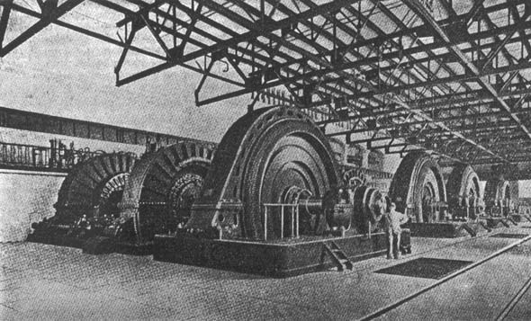
| Interior of A Niagara Falls Generating Station, Showing 10,000 Horsepower Generators. |
It is coming to be generally recognized that lightning protection is not a matter of some simple device to be attached to a system at one or two points, but that the disturbances which are involved are such as require much more general and radical consideration. The design of transformers, of terminals, of switching appliances and of insulators are all involved. The location of the lines, the form and character of the supports for the wires, the protection of the line itself, as distinguished from the apparatus at its terminals, are all elements in the general problem.
In many of the transmission systems the troubles from lightning are not station troubles but line troubles. The apparatus in the station does not suffer, but some part of the line remote from the station. Wooden poles are shattered or burned. Insulators are punctured. Iron pins and iron poles protect the structure, but make the insulator more vulnerable. In the contention between iron structures and wooden structures neither side has all the argument nor all the favorable experience.
Two methods of line protection are receiving practical consideration the installation of line lightning arresters to remove the excess potentials, and the installation of static shields in the form of grounded wires over the transmission wires to prevent the accumulation of the high potentials. Line construction for normal conditions is comparatively easy. It is the storm, with its sleet and wind, to test mechanical strength, and with its lightning flash or stroke to try the integrity of the insulator, which makes the problem so difficult. The haven of safety for the wires is the earth, and if the wires cannot be put underground, then the ground should be put over the wires.
This problem of line protection from static disturbance is one of the most serious in transmission development, having to do so vitally with continuity of service.
CONTROLLING DEVICES.
The switching and controlling devices on the high-voltage circuits, which became necessary when the transmission system developed from a line connecting the power house with a single sub-station into a network of many lines and many stations, furnishes in itself material for an extended article. Oil switches; fuses, notably those of the expulsion type; disconnecting switches; station wiring, with compartments for the high-tension bus-bars and wires all have increased in capacity and efficiency. A radical departure in station arrangement is now proposed by which the bus-bars, high-tension connections and transformers will be located out of doors.
THE DEVELOPMENT OF THE ART.
The steps which have marked the progress from the transmission of a hundred kilowatts at 10,000 volts to the systems of today have been little steps. They have not been taken by one man, nor by one company, but by many men in many places. Theoretical study, painstaking experiment, wide-spread observation and experience, have all contributed. The freedom with which designing and operating engineers have interchanged their knowledge and experience through the reading and discussion of papers has been an effective element in this advance. There are few departments in which engineering co-operation has been more extended and has been fruitful of larger results than in power transmission.
Great as have been the developments which have taken place in the details of the various elements involved in power transmission, they are equaled by the general commercial development, by the amount of money which is invested in transmission systems, by the general confidence in which long-distance power transmission is now held, and the substantial place it is now assuming in modern affairs.
In looking back over the last few years we note the very great development which has taken place. There is no indication now that the limits have been reached. The fact that the principal increases have been made in size, until recently, when new types are being introduced, is significant of the kind of changes which the future may have in store. The introductory sentence of a recent paper by Mr. Frank G. Baum before the American Institute of Electrical Engineers is significant and will bear careful thought: "In designing power-transmission systems it is always well to bear in mind that the ultimate development of the art and of the country has not yet been reached."
