[Trade Journal]
Publication: Western Electrician
Chicago, IL, United States
vol. 42, no. 8, p. 153-154, col. 1-3,1
Tusciano River Hydro-electric Plant in
Italy.
BY A. DE COURCY.
One of the recent power-transmission plants to be erected in the southern part of Italy is the Tusciano station, which is controlled by the Southern Electric Company. The power house is situated near the village of Olevano, about four miles from the railroad station of Battipaglia, and it utilizes, the power of the Tusciano River in order to operate a power line on the high-tension, alternating system and to distribute current to the industrial centers of Salerno, Nocera, Scafati and Torre Annunziata. The last named lies at a distance of 37 miles from the central station. The electric outfit of the present plant has been furnished by the Societe Aronyme Westinghouse and constructed at its works at Havre.
Tusciano River rises on the southern slope of the range formed by the Accellica, Cervialto and other mountains and flows into the sea near Battipaglia. Its basin, as well as that of its main affluent, the Isca della Cava, lies in an open region with but little forest, and on this account the freshets are sudden and large. On account of the nature of the ground to be traversed, as well as the great length of the intake canal, the Franco-Swiss company, which carried out the construction work, decided to build the canal entirely underground. The dam lies at a height of 431 meters above sea level, and the water is led off on the right bank of the river at 20 meters above the dam. Near this point is the first basin, placed below the dam. Connected with it by a gate is a second basin, from which starts the offtake canal. This canal is 3.6 miles long. At the end of it is a settling basin which is connected in turn with two main reservoirs. From each of the reservoirs there will be a penstock leading to the power house. The head of water is 283.9 meters and the total amount of power which can be utilized is 13,247 horsepower. But as the whole amount is not used by the Southern Electric Company, this company has only 7,190 horsepower, which corresponds to 5,400 horsepower upon the turbine shafts. At present there is but a single penstock constructed, and the general disposition of this part of the plant will be noticed in one of the accompanying pictures. The penstock ends at the station in a general distributing pipe which supplies the different turbines.
| |||
| (Left) View in Generator Room of Power House. (Right) Generating Station Near Village of Olerano. Switchboard Controlling the 3,000-Volt Generators. Tusciano River Hydro-Electric Plant in Italy. |
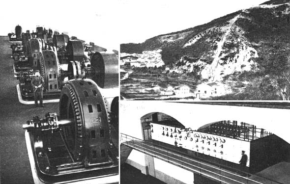
The power house contains a generator room which is 44 meters in length and 12.50 in width, and also a wing in the front part in which are located the transformer room, a repair shop and other annexes. The stories above these rooms are used for offices and also to contain the main high-tension switchboard. Five turbine waterwheels have a capacity of 1,400 horsepower each and are coupled upon a horizontal shaft to the main alternators, while two small 150-horsepower wheels are used for the exciters. The turbines operate at a standard speed of 500 revolutions per minute. Each is provided with a motor governor for operating the water feed. This type of governor is entirely mechanical in its action and has some advantages over the usual hydraulic piston governor, especially when the water contains sediment. A hand-operating device is also used in connection with the governor, which serves for starting and stopping the wheels, and by a proper arrangement the attendant cannot close off the water too quickly, thus avoiding any shocks to the water column in the penstock. These wheels have an efficiency at full load of 76 per cent., varying down to 62 per cent. at one-quarter load. About 10 tons is the weight of each turbine, and it is connected to the alternator by an electric disk coupler.
Turning to the alternating-current generators of the plant, which will be observed in one of the pictures, it will be noted that these machines are of the revolving-field, horizontal-shaft pattern, and furnish current of 3,000 volts and 50 cycles on the three-phase system. The field winding is made up of copper strips and the poles have air circulation gaps which correspond to similar openings in the armature. Apparatus of the Leblanc system is used with these machines for connecting in parallel. The drop in voltage between no load and full load for the usual voltage, and constant speed is 6 1/2 per cent. for cos Ø = 1 and 20 per cent. for cos Ø = 0.8. The weight of the armature portion of each alternator is very nearly eight tons, while the revolving field and its shaft weigh 6.3 tons, and the bed-plate and bearings figure for 6.1 tons. Although the peripheral speed in this case is relatively high, being 45 meters per second at the standard speed of 500 revolutions per minute, there is no difficulty from this cause, and they have been run on test at as high a speed as 800 revolutions per minute, which corresponds to the racing of the turbines.
The exciters are compound-wound, four-pole machines, rated at 110 kilowatts, and furnishing 110 volts when running at the normal speed of 700 revolutions per minute. Lighting current for the station is also given from these circuits and several motors are run in the repair shops.
The 3,000-volt current from the alternators is raised to 30,000 volts by means of three groups of transformers. Each group comprises three single-phase static transformers, these being placed in an adjoining room. These transformers are of the oil-insulated pattern without artificial cooling, and their weight, together with the oil, is six tons. They are connected in delta upon the bars of the alternators and in star upon the terminals of the pole-line, which transmits current at 30,000 volts. By connecting them in delta for the latter, case the operating voltage can be limited to 17,500 volts if desired.
There are three main switchboard frames in the station. One of these contains the 3,000-volt panels for the machine current, while the second receives the 30,000-volt current from th.p transformers. A third switchboard carries the low-tension apparatus.
The overhead line is formed of electrolytic copper wire of seven-millimeter gauge. At present there are two lines of three wires each. Where the lines leave the station they are placed parallel to each other and in the same horizontal plane upon a long iron beam held upon two latticework poles, at the extremities of which are placed two lightning arresters of the horn pattern. From this point the wires go to the main poles of the line. The latter are all of metallic latticework construction and have three cross-arms upon which the insulators are fixed so as to have one line on the right and the other on the left of the pole. About 60 centimeters distance is allowed between the wires and the poles are spaced 60 meters apart on the average.
 |
| Insulator for Tusciano River Transmission Plant in Italy. |
A distance of 38 miles is covered by the present line. Starting from Olevano, on the Tusciano River, it runs to the villages of Salerno, and Vietri, passing thence to Cava Dei Tirreni and crossing the railroad, then following the north slope of the Mount Albino and descending to the plain near Scafati. It then passes along the railroad until it reaches the sub-station, which is situated near the railroad station of Torre Annunziata. In the accompanying diagram is represented the type of insulator which is used for the pole-line, and it has been recently adopted as an improvement over the insulator formerly used, which was found to be of insufficient strength. The present insulator is made up of two pieces of porcelain cemented together by a litharge and glycerine cement, while the insulator is fixed to the metallic rod support by a threaded brass cap. Referring to the drawing (A) is the porcelain, (B) cement, (C) the threaded cap. A series of tests were made with these insulators. For the perforation the two parts separately stood 50,000 volts, and the two pieces assembled 100,000 volts. For the exterior arc, under rain falling at 45 degrees at l.0 millimeter per hour, no arc is produced at a tension of 45,000 volts. As to mechanical resistance, under a tractive effort of 800 kilogrammes, neither the porcelain nor the metal parts was found to suffer. The joints of the wires are made by means of Hoffmann joints with melted tin run into them.
In the portion of the transmission line lying between the main station and the town of Pontecagnano the poles carry a third line working at 3,000 volts which is used to supply several industrial establishments, among which may be mentioned the agricultural plant of the Campione firm.
The sub-stations on the line are divided into two stories, the lower story containing the transformers and the upper the switches, lightning arresters, fuses and other apparatus. The windings of the transformers allow of reducing the line voltage of 30,000 volts to 2,000, 1,000 and 500 volts, according to circumstances, by a simple change in the secondary winding, while if need be the primaries can be modified so as to take 17,000 volts as a standard line voltage.
