[Trade Journal]
Publication: Electrical Age
New York, NY, United States
vol. 37, p. 171-177, col. 1-3
The Electrical Plant of the Canadian Niagara Power Company
by H. W. Buck
A Paper Read at the Recent Convention of the Canadian Electrical Association
THE plant of the Canadian Niagara Power Company was the first of the power houses on the Canadian side of the falls to be designed and to have construction work begun upon it. As soon as the decision was made to go ahead with this development the question was raised as to whether the plant should be identical with those of its allied company, the Niagara Falls Power Company, on the American side, or whether engineering advances had taken place since their completion sufficient to justify changes and improvements. In general, it was decided to adopt the same system of development, but certain essential changes were introduced, as follows :—
Generating units of 10,000 H. P., instead of 5000 H. P., were adopted. The generated voltage was raised to 12,000 volts. The generators were wound for 3-phase instead of 2-phase.
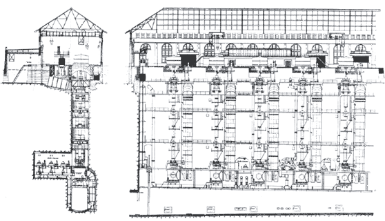 |
| Fig. 1.—Sections of the Power House and Wheel Pit of the Canadian Niagara Power Company, Showing Equipment |
When the 10,000-H. P. generators were ordered for this development they constituted the record to date for capacity, and were for a short time the "largest in the world,'' but, like all records in electrical work, it was of short duration. At present there are a number of machines in operation somewhat larger than these in rating, and others are being seriously considered for certain installations which will be nearly twice as large.
It was decided to change from 5000 H. P. to 10,000 H. P. for the generating units, in order to reduce the length of the wheel pit, power house, forebay, etc., and consequently to reduce their cost of construction, and to reduce the cost per H. P. of the generators, water wheels, etc.
The load of the Niagara Falls Power Company and its ally, the Canadian Niagara Power Company, had become so large that a unit of 10,000 H. P. could be installed without having such unit represent too large a proportion of the total load, from the standpoint of convenience and flexibility of operation.
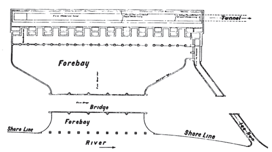 |
| Fig. 2.—General Plan of the Canadian Niagara Power Company's Development |
The decision to have the generators wound for 12,000 volts was made to effect economies in station wiring and in the system of underground distribution necessary to transmit the power from the power house outside the limits of the Victoria Park. The particular voltage of 12,000 was selected as being the highest which at that time was considered reasonably safe for underground service, and also because the Niagara Falls Power Company had already adopted this as a transformed voltage for the transmission of power to some of its local customers.
Three-phase was taken instead of the two-phase winding of the American machines on account of the simplification of switches, wiring, etc., and also to effect the saving of 25 per cent, in transmission copper.
HYDRAULIC MACHINERY
The general hydraulic construction of this plant is very similar to that of the American plant, which is too well known to engineers to require detailed description here. Fig. 2 shows a general plan of the development. Fig. 1 shows sections of the power house and wheel pit, together with their equipment.
The turbines were all designed by Escher Wyss, and the first three wheels were built at Zurich. The last two were built from the same designs by the I. P. Morris Company, of Philadelphia. The turbines are of the Francis type, inward discharge, with draft tubes led to the bottom of the wheel pit, as shown in Fig. 1.
A regulating gate is installed at the end of the wheel pit to maintain the level of the tail water at a sufficient height at all loads to cover the mouths of the draft tubes. This regulating gate is operated by an 85-H. P. direct-current motor, hand controlled. The weight of the rotating machinery is carried by an oil thrust bearing under the dynamos, and also by an hydraulic piston at the bottom of the turbine. At fullgate opening at a head of approximately 135 feet, the turbines give an output of about 12,000 H. P.
ELECTRIC GENERATORS
The generators are of the internal revolving-field type with 12 poles, giving 25 cycles at 250 revolutions per minute. The details of construction of the generator are shown in Fig. 3. The efficiency at full load is about 98 per cent., and the regulation on full non-inductive load about 8 per cent. The generators were built by the (ieneral Electric Company, a large part of the assembly work being carried out in the power house. The armatures are Y-connected, and the neutral is brought out so that it can be grounded if desired.
SWITCHBOARD
From the generators the current is led through varnished cambric insulated cables to double-throw selector oil switches, and thence to the bus-bars, of which there are four sets. The oil switches are electrically operated by relay switches placed on the main switchboard panels. Fig. 5 shows a general section through the switchboard gallery, and indicates the relation between controlling panels, oil switches, bus-bars, etc.
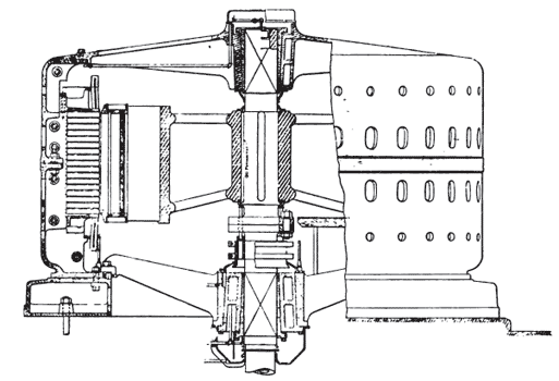 |
| Fig. 3.—Cross-Section of One of the Generators Built by the General Electric Company of Schenectauy, N. Y. |
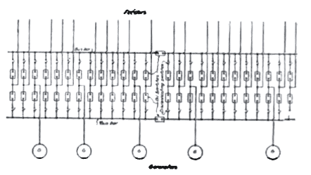 |
| Fig. 4.—General Wiring Diagram of the Circuits Connected With the First Five Units |
The controlling and instrument board consists of 5 generator panels, 20 feeder panels, 10 recording wattmeter panels, and 3 bus-bar interconnecting panels. Each panel is distinct, and contains no instruments or switches except those belonging to the particular feeder or generator in question. In this regard it is different from most of the switchboard arrangements adopted in modern plants.
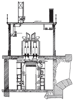 |
| Fig. 5.—Section Through Switchboard Gallery |
The so-called "bench-board" system of operation usually installed economizes space, but it has certain disadvantages. The concentration of instruments and relays necessitated in this construction may cause considerable confusion at times of emergency. If instrument needles suddenly begin to slam around on their scales, it is somewhat difficult to make a prompt and correct association in a bench-board installation between the instruments and the relay switches involved, which are usually on slabs separate from the instruments. With the panel construction adopted in this plant, possibly more space is occupied by the board itself, but operating simplicity and directness results.
Each panel contains within its limits all the instruments and switches involved in any operation which the attendant has to make, and consequently there is a minimum liability to confusion and mistake. The separate panel construction also permits the separation of control wires, which become so congested in the bench-board arrangement. In case of an accident in the power house there is consequently less likelihood of a complete crippling of the control system.
 |
| Fig. 6.—Showing General Construction of Manholes and the Grouping of Ducts |
 |
| Fig. 7.—Showing Method of Connecting the Three-Phase, 12,000-Volt Canadian System With the Two-Phase, 2400-Volt System of the Niagara Falls Power Company Through Scott Connected Transformers |
The present equipment of the power house comprises five machines, and this group and its switchboard is considered as a complete plant. When the power house structure is extended to its full length, six more 10,000-H. P. units will be installed, having an entirely separate switchboard, separate exciter plant, etc. This separation is made for the reason that 50,000 H. P. is believed to be as large a block of power as should be under the control of a single switch-board and its attendant.
EXCITER PLANT
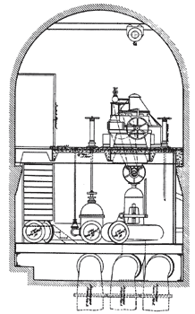
The exciter plant is located in a compartment near the bottom of the wheel pit at the turbine deck level. There are three 200-KW, 125-volt d. c. generators, each connected to an independent turbine. Any two of these units will carry the entire direct-current load of the power house. There are two sets of exciter bus-bars, one of which operates the generator fields and the other the d. c. power system, including motors and arc lights. The current is carried up the pit to the main floor of the power house through a system of vertical copper bars supported every 10 feet. Fig. 8 shows the general arrangement of this plant.
 |
| Fig. 8.—General Arrangement of the Exciter Plant |
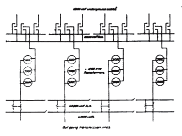 |
| Fig. 9.—Diagram of Connections of Transformer House Circuits |
UNDERGROUND CABLE SYSTEM
All the power from the power house is transmitted underground by means of No. 000 B. & S. paper-insulated triplex lead-covered cables. The feeders are divided into two groups. One set leads from the north end of the power house through Victoria Park and across the arch bridge to the plants of the Niagara Falls Power Company, with which the feeders are interconnected. The other group runs south up the high bank above the power house to the transformer house there located.
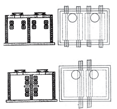
The conduits are constructed in four groups of eight ducts each, this segregation being in order to separate the cables in the manholes, and consequently reduce to a minimum the risk of damage from short circuit and also to prevent overheating of the cables in the ducts, the separation of the groups facilitating the conduction of heat in the ground. In no case is the group wider than two ducts, so that every duct has the ground in contact at least on one face.
The cables are rated at a maximum of 4000 H. P. each at 12,000 volts. This rating corresponds to about a 40-degree C. rise in copper temperature when all the cables in the group are in service at full load. Fig. 6 shows the general construction of manholes and grouping of ducts. The manholes are all made double with a concrete fire wall between the two halves, so that in case of a destructive manhole short-circuit, not more than one-half the feeders could be involved.
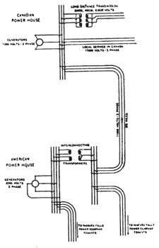
Fig. 7 shows the method of interconnecting the three-phase 12,000 volt Canadian system with the 2400 volt two-phase system of the Niagara Falls Power Company through Scott connected transformers. The two systems are constantly in operation in parallel through this connection, and no trouble is experienced from pumping or in controlling the distribution of load.
 |
| Fig. 10.—Diagram of Windings of the 1250-Kw. Transformers |
TRANSFORMER HOUSE
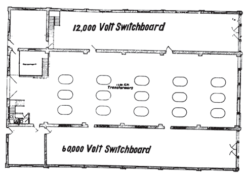
Fig. 11 shows the general arrangement of the transformer house and its equipment. The installation comprises twelve 1250-K.W. transformers, each bank therefore requiring one-half the output of a generator at the power house. Transformers of comparatively small size were installed for reasons of flexibility of operation. The very large transformer units now being used in some plants cost considerably less per KW., but the large size of units makes it difficult to isolate circuits and bus-bar sections so necessary at times in the operation of a plant.
 |
| Fig. 11—Plan of Transformer House, Showing Arrangement of Equipment |
The building is divided into three sections. The east bay contains all the 12,000 switches and bus-bars, the central bay contains only the step-up transformers, and the west bay the 60,000-volt switching apparatus. The transformers are of the oil type, water cooled, the water supply being insured by a storage standpipe adjacent to the transformer house, with sufficient capacity to operate the transformers for 48 hours in case of a waterworks shut-down. Fig. 9 illustrates the general scheme of connections of the transformer house circuits.
 |
| Fig. 12.—Section of Insulator for the Buffalo Transmission Line. Manufactured by the Electrose Manufacturing Company, Brooklyn, N. Y. |
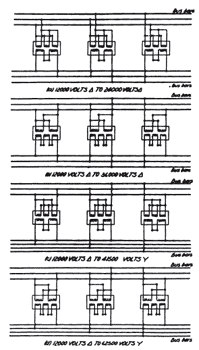
The arrangement of windings on the 1250-K.W. transformers are somewhat unusual. Fig. 10 illustrates the arrangement. The transformers are constructed with five similar coils, two of which constitute one winding and three the other winding, either of which can be used interchangeably as a primary or secondary. By the various combinations of coils, as shown in the sketch, any of the following voltage ratios can be obtained with the full copper efficiency of each coil:—
12,000 volts delta to 24,000 volts delta
12,000 volts delta to 36,000 volts delta
12,000 volts delta to 41,500 volts Y
12,000 volts delta to 62,500 volts Y
The west bay of the building also contains 3000 H. P. in air-blast transformers, which lower the generated voltage from 12,000 to 2400 for distribution of power to several small consumers in the city of Niagara Falls, Ont., to whom it would be unsuitable to deliver power at as high a voltage as 12,000 volts. This distribution at 2400 volts is by an overhead line.
All the high-tension wiring in the transformer house is insulated for the highest voltage, 62,500 volts, and the conductors are of sufficient current-carrying capacity for operation at full output at the lowest transformer voltage, 24,000 volts.
 |
| Fig. 13.—Pole for the Buffalo Transmission Line. |
BUFFALO TRANSMISSION LINE
The output from this transformer pins are malleable castings secured house will be used partially for transmission at 24,000 volts to Fort Erie, and thence across the Niagara River to Buffalo, the distance being about 15 miles. There are some engineering features connected with this work which may be of interest.
The transmission line is built on a private right of way 30 feet wide extending from the transformer house to the River front at Fort Erie. There will be two pole lines on this right of way, each carrying two circuits. The circuits have a nominal rating of 12,500 H. P. each at 24,000 volts, making 50,000 H. P. total for the transmission.
The poles used are shown in Fig. 13, and consist of two 4-inch wrought iron pipes, jointed together at the center, as shown, by a casting which has four struts projecting radially at 90-degree angles. Truss rods secured at the top and bottom of the poles pass over the ends of these struts, which, when tightened up, stiffen the jointed pipe. The function of this central tubular member is to resist downward compression only.
The horizontal stresses on the pole are resisted by four guy rods anchored in the ground with concrete guy stubs. There is one of these guys in each quadrant around the pole. Under the central member of the pole is placed a heavy block of concrete which carries the iron step for the central pipe and takes the thrust. All the castings are malleable. The cross-arms are made of channels of special section; and the pins are malleable castings secured through the cross-arms by nuts on the bottom.
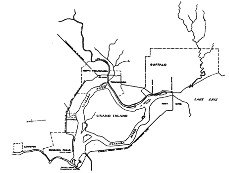 |
| Fig. 14.—Map Showing Right of Way of the Buffalo Transmission Line |
This type of pole is very strong and very economical in iron. The central member is under direct compression only, and the guys are under direct tension, which stresses require the minimum amount of material to resist. There are no lapped joints to rust out, and the sections are all large enough to withstand considerable corrosion without weakening. The poles are 40 feet in height, and are placed apart at distances ranging from 250 to 300 feet. Fig. 14 shows a map of the transmission line right of way.
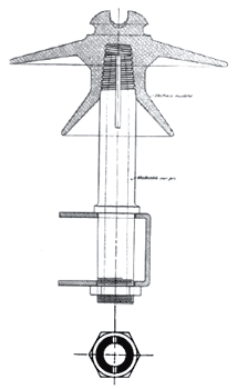
The insulators shown in Fig. 12 are made of a compound known as "electrose." This material is a very good insulator, is very strong mechanically, and is entirely free from cracks and other defects which are common in glass and porcelain. Similar insulators have been used on the Buffalo transmission lines of the Niagara Falls Power Company for the past three years, and they are the only insulators on those lines which have caused no trouble. It is impossible to shatter electrose insulators by stone throwing, and they will frequently turn a rifle bullet without being damaged seriously. The conductor used on this line is of aluminum, 500,000 cir. mils in section and having 37 strands.
At Fort Erie the line is tapped by a connection to a local sub-station for the supply of power to that municipality. The line then rises from the standard 40-foot elevation to a tower 80 feet high, erected about 1200 feet from the Canadian shore line of the Niagara River. Thence the line rises again by a single span of 1200 feet to a tower on the river bank 210 feet in height. Thence by another single span of 2300 feet the line passes to the Buffalo side of the river to another 210-foot tower. From there it drops down to a new 50,000-H. P. terminal house constructed for the distribution of this power in Buffalo.
 |
| Fig. 15.—The Long Span Over the Niagara River, 1200 Feet to the First Tower and From That 2,300 Feet to the Buffalo Shore |
Fig. 15 shows the general profile of this long span crossing; 500,000-c. m. 61-strand aluminum cable is used. Each wire is secured to the top of pole B on an insulated support. At towers A and C the lines are attached through strain insulators to steel cables, which pass over sheaves about 24 inches in diameter, and thence to weights which are equal to the tension on the wire in pounds, amounting to 4500 pounds on each line. The live portion of the line passes down the tower from the outside of the strain insulator to the terminal house on the Buffalo side and to the main transmission line on the Canadian side.
The object of this arrangement is to obtain a maximum clearance above the water with a minimum height of tower. By keeping the span under constant tension the deflection becomes independent of variations in temperature and also independent of wind stress allowance. In a fixed span of this length the increase in deflection in summer, due to the heat of the sun, would amount to at least 40 feet. With the weight and sheave arrangement the deflection is maintained constant at the minimum. At times of heavy wind stress the weights will rise and prevent the tension in the cable from ever exceeding the predetermined amount equal to the balance weight.
The power house has been in successful operation for about a year, and five generators are now in service. The transmission lines to Fort Erie and Buffalo are now in process of construction, and are expected to be placed in service about the first of November.
