[Trade Journal]
Publication: Electrical Age
New York, NY, United States
vol. 37, no. 1, p. 11-22, col. 1-3
The Power-Transmission System of the Long Island Railroad
By. W. N. SMITH
GENERAL FEATURES OF THE POWER TRANSMISSION LINE.
THE lines of the Long Island Railroad first equipped with electric power comprise the Atlantic Avenue division between Flatbush terminal and Belmont Park, and the Rockaway Beach Division between Woodhaven Junction and Rockaway Park. The equipment of the latter division has also been ex-tended to enable electric operation via Far Rockaway and Valley Stream.
A study of the traffic conditions to be met by the electric equipment upon these divisions resulted in a preference for sub-station sites at Woodhaven Junction, East New York, Flatbush Avenue, Rockaway Junction, and Hammel. These were ultimately selected as permanent sub-station locations, except that Grand Avenue, about one mile out from the terminal, was later substituted for Flatbush Avenue. Since the original installation described in this article was completed, a sixth sub-station has been located at Valley Stream, receiving its power from an extension of the overhead line by way of Springfield Junction.
Two portable sub-stations were also provided as the most economical method of supplying current for the very heavy periodic traffic to and from the Metropolitan race track south of Jamaica, and the new Belmont Park race track about five miles east of Jamaica. These loads occur for two hours each day, for periods of two weeks, twice a year. The portable sub-stations consist of 1000-K. W. rotary converter outfits, complete with transformers and switch-board, each mounted in a heavy steel box car.
In reaching a decision as to whether the overhead or under-ground type of construction should predominate, a very careful study was made of the record of experience in operating lines of great length and of large carrying capacity. It appeared that the troubles in overhead lines were generally from the following causes: Wind, lightning and sleet storms; structural weakness of poles, cross arms, pins and insulators; outside interference either from branches of trees or mischief makers and thieves; and very rarely, by heat from a conflagration close to the route.
| |||
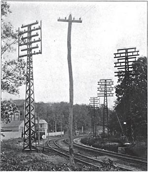
| Fig. 1. the Transmission Line of the Long Island Railroad Crossing A Track. the Cable Retainers Are Shown on the Pole at the Left. |
In case of conduit construction, it was found that breakdowns were generally due to capacity effects causing extraordinary voltages, to depreciation of cable sheaths from electrolysis, or to short circuits by reason of mechanical injury, imperfect insulation, or failure of joints, and occasionally to overloading or to gas explosions in manholes.
Comparing the causes and effects of the troubles in the two classes of construction, the general conclusion was reached that, while an over-head line is liable to more frequent interruption through minor troubles than an underground line, the interferences with continuous operation on an underground line, when they do happen,, are likely to be of a more serious character, and of longer duration. Although underground construction might have been preferred, could its cost be brought down to something like an equality with over-head costs, financial considerations favour the adoption of the overhead type because its cost is only a fraction of that involved in high-tension cable and conduit work, and because its reliability is assured when properly installed. Overhead construction was therefore adopted wherever it was usable.
The topography of the system is such that the Woodhaven Junction sub-station becomes a natural distributing center between the power house and the other sub-stations. The problem of line construction was therefore to build a trunk line from the main power station to Wood-haven Junction, with two branch transmission lines running along Atlantic Avenue between Grand Avenue and Rockaway Junction with two subordinate branches from Rockaway Junction to the two race tracks, and a third subordinate branch running directly south from Woodhaven to Hammel sub-station, across the Jamaica Bay trestle.
The impracticability of constructing high-tension overhead lines in thickly populated sections of Brooklyn and Queens, required recourse to underground construction in two sections of the line. Except where submarine cables were used at the drawbridges in the Jamaica Bay trestle, the remainder of the transmission line is of the overhead type of construction.
The trunk line as originally built carries five circuits from the power station to Woodhaven junction sub-station, running part of the way in an eighteen-duct conduit line and the remainder on a line of steel poles.
The general arrangement of the transmission circuits is shown in Pig. 3. It will be noted in this diagram that the incoming trunk line circuits at Woodhaven Junction are distributed along a set of bus bars called the "transfer buses," and divided into sections from which the outgoing transmission circuits lead in various directions. It is possible by manipulation of the bus junction switches to operate these circuits separately or together, from outlying sub-stations all the way back to the power station. The same general arrangement is carried out in a smaller degree by similar transfer buses at East New York and Rock-away Junction.
The lengths of the various sections of the transmission lines are as follows:-
Conduit section of trunk line, power station to Dutch Kills Street, 1.12 miles. Overhead trunk lines. Dutch Kills Street to Woodhaven Junction, 7.85 miles. Conduit section from Woodhaven to East New York, 3.23 miles; from East New York to Grand Avenue, 3.04 miles; from Woodhaven to Dunton, 1.7 miles. Overhead from Dunton to Rockaway Junction, 1.73 miles; Rockaway Junction to Belmont Park, 3.71 miles: Rockaway Junction to Springfield Junction, 3.55 miles; Springfield Junction to Valley Stream 2.57 miles; Woodhaven Junction to Hammel, 6.98 miles. The total mileage of conduit lines now in use is there-fore 9.09, and that of pole lines 26.19 miles.
CONDUIT CONSTRUCTION
Between the power station and the railroad tracks, part of the conduit construction was rendered especially difficult because much of it was situated below the level of the ground water, which, for a large part of the distance was nearly at the surface, so that special provision for the drainage of the ducts and manholes was necessary.
The manholes in this part of the line are connected by a line of 8-inch sewer pipes laid beneath the ducts and entering the manholes about 18 inches from the bottom, thus forming a catch basin to prevent silt or other foreign matter from getting into and clogging the pipes. This conduit line is so pitched as to bring all the drainage into three sumps, one located at the power station, one about one-half mile from it, and the third near the Dutch Kills Street end of the conduit line. These sumps are kept pumped out by electrically driven submerged centrifugal pumps, automatically controlled and discharging into the city sewer system.
This conduit line is constructed of single vitrified clay ducts 18 inches long, with square holes 3 13-16 inches inside measurement, and walls inch thick. They were designed especially for this construction, and the ducts are 7-16 inch greater in diameter than usual in order to facilitate the installation of the three conductor high-tension cables, which are nearly 3 inches in diameter.
A single duct was preferred to multiple ducts because of the thicker wall between ducts, which is better able to resist heat in case of a possible short circuit. A square hole with rounded corners was preferred as affording space for dirt and pebbles to slide to one side instead of being dragged along underneath the cable and injuring the sheath as would be the case if round ducts had been used. The ducts are laid in cement mortar in such a way as to break joints in all cases, and are surrounded on the top, bottom, and sides by a covering of concrete 4 inches thick composed of one part Portland cement, 2 1/2 parts sand and 5 parts broken stone. The ducts are arranged three wide and six high.
Manholes for drawing in and splicing the cables are located 400 feet apart on straight work and a shorter distance apart on curves. The standard manhole for straight line work is 8 feet long, 4 feet wide, and 6 1/2 feet high, inside dimensions. The corners are cut off so that a horizontal section of the manhole resembles an elongated octagon.
UNDERGROUND CABLES
The underground high-tension cables are of the three-conductor type, each conductor having a cross-section of 250,000 c. m., and being composed of 37 copper wires. Each conductor is covered with a wrapping of impregnated paper 7-32 inch thick. The interstices between the insulated strands are filled in with jute insulation and another layer of 7-32 inch thick paper insulation is wound over the entire group. The outside sheath is 9-64 inch thick, and is composed of lead with about 1 ½ per cent. of tin added. The completed cable is 2 7/8 inches outside diameter.
Each length of the cable was tested at the factory by applying 30,000 volts between each pair of conductors, and between each conductor and the sheath. After the cable was installed in the ducts and jointed up ready for service, it was again tested by applying between each pair or conductors 30,000 volts, and between each conductor and the sheath 27,000 volts for a period of 30 minutes. At each end of every high-tension cable there is sweated on a spun brass end-bell, which is filled with "No. 67" G.E. compound, to properly seal the ends of the cable and pre-vent injurious static discharges. The end-bell is about 7 3/4 inches in diameter and about 7 inches high. The three conductors are brought out separately through a wooden head in the end-bell, after being wrapped with varnished cambric tape, and are surrounded by micanite tubes to give additional insulation.
At the drawbridge in the Jamaica Bay trestle, the cables are of the armoured submarine type, and the conductors are insulated with 7-32 inch of rubber around each strand with another 7/32 inch of rubber around the group of three. This insulation is composed of 30 per cent. pure Para rubber and is covered with a sheathing 9-64 inch thick, and composed of lead with about 1 1/2 per cent. of tin added. Over this is an armour of No. 4 B. & S. galvanized iron wires laid spirally on the outside of the lead covering with a thin layer of jute between the lead and the armor. There are two such cables at each drawbridge.
The high-tension cables are located in the lower portion of the conduit system wherever possible with the idea of separating them from any other cables for different purposes which may be installed subsequently. They are carried around the sides of the manholes in racks. The mini-mum radius of the bend in this type of cable is 18 inches. At each man-hole, there is a strip of sheet copper sweated on to the lead sheath of the cable and brought out through the wrappings to allow of grounding the cable should it be necessary to protect it from electrolysis.
Before the cables were pulled into the ducts, a wooden mandrel 3 feet long and 3 1/8 inches in diameter was pulled through to insure a clear passage. At the Jamaica Bay drawbridges, the armoured cables were laid across the channel and al-lowed to settle to the bottom. A diver then arranged them so that they were properly separated, and they were sunk into the mud by means of a water jet, supplied by pumps at 100 pound pressure. By means of this jet, the diver was able to scour out a trench wide enough to contain the cables, 4 feet below the bottom of the channel.
This method of installation was preferred to dredging, because of the difficulty which would have been encountered in attempting to dredge the trench through the fender piles on either side, and because of the rapid current through the channels, which would fill with sand a trench so dredged immediately after excavation, unless the cables should be laid (luring the dredging process, which is obviously impracticable.
There is in all about 25 miles of high-tension underground cable installed, besides 0.418 mile of armoured submarine cable.
ARRESTER HOUSES
The vulnerability of underground cables to lightning and to other static disturbances set up in the line require that the outlying ends of cables exposed to lightning discharges have protective apparatus.
Whenever the underground cable section of the transmission line is joined up with the overhead system, lightning arresters and choke coils are installed, and suitable houses are provided to shelter - this apparatus. There is one on the main transmission line at Dutch Kills Street, Long Island City, and another at Dunton, on the branch line running east of Woodhaven. Smaller houses were also provided for the same purpose at the two drawbridges.
| |||
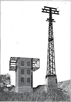
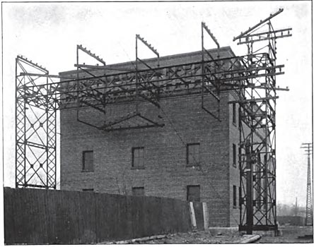
| Fig. 2. An Arrester House at Dunton. Whenever the Underground Cable is Joined to the Overhead System, Lightning Arresters and Choke Coils Are Installed in Suitable Houses. |
The house at Dutch Kills Street is a fireproof brick structure, with a concrete floor and roof; it is 33 1/2 feet in length. 17 1/2 feet wide, and 30 1/2 feet high inside. This house at present contains room sufficient for eight out-going overhead circuits which leave the house four on a side. The general design of the transmission line is such that the circuits on one side of the poles can be shut down for repairs without shutting down those on the other side, and this idea was carried out in the construction of the arrester house, so that there would he no confusion possible between live and dead conductors whenever it might become necessary to do any repair work on the line.
The arresters are all provided with knife switches, so that they can be readily disconnected from the circuit. A choke coil is also provided in series with each main circuit, and another knife switch between the choke coil and the cable bell, enabling the cable to he entirely disconnected from the overhead line.
The ground connections all run to a single ground lead consisting of 5 1/2 square feet of copper plate buried in the ground between layers of crushed coke. The arresters are of the Westinghouse low equivalent type mounted on marble slabs, which in turn are carried upon porcelain insulators.
The outgoing cables on each side are anchored on a strain pole after leaving the racks upon the sides of the building, which in themselves are not intended to carry the longitudinal stresses of the overhead cables.
The openings in the side of the house through which the cables run are 18 inches square, enclosed by two glass plates 3/8 inch thick and separated 5 inches with 2 1/2 inch holes in the centers, through which the cable passes without touching the glass. A thin disk of brass 2 1/2 inches in diameter is attached to each wire midway between the glass plates, and thus prevents the direct access of rain or snow through the openings. Standard straight line insulators are used for supporting the bare wires inside of the building.
The arrester house at Dunton is shown in Fig. 2. Here the branch' transmission line running eastward from Woodhaven is changed from conduit to overhead construction. The design of this house and the arrangements of the apparatus inside it are identical with the one just de-scribed, but with capacity for six circuits instead of eight.
At the drawbridge channels in Jamaica Bay. three houses are provided to shelter similar apparatus. Each consists of a steel framework covered with expanded metal and concrete side walls and a corrugated copper roof resting on a pile foundation.
OVERHEAD LINE CONSTRUCTION
There are two general divisions of the overhead construction.-the trunk line between Dutch Kills Street and Woodhaven Junction, and the branch lines between that point and the other outlying sub-stations. The trunk line is built of steel poles, and the branch line between Dunton and Rockaway Junction, through which the latter sub-station and two portable sub-stations are fed, and upon which the circuits to stations not yet constructed may eventually run, is also equally important with the trunk line and is therefore built of steel.
From Rockaway Junction, the branch pole lines to the separate out-lying sub-stations are of wood. From Woodhaven Junction south, the poles are of steel to the southern outskirts of Ozone Park, because of the rather exceptional height at which the cables have to be carried to clear other wires, but from Ozone Park to Hammel they are of wood.
 |
| Fig. 3. Diagram Showing the General Arrangement of the Transmission Circuits. |
The trunk line is designed to carry eight three-phase transmission circuits consisting of three 250,000 C. M. cables each, together with eight low-tension cables of 500,000 c. m. each. As the latter when installed must be 25 feet above the ground, and as there must be a reasonably clear space between the low and the high-tension circuits, steel tower construction is necessarily used.
The branch line transmission circuits, however, are not intended to carry more than two three-phase transmission circuits and four low-tention cables on a single line of poles. This condition enabled the use of wooden poles, of which an extra heavy type was selected for stability.
STEEL POLES
The steel poles are of various sizes to meet the different conditions. They are all designed to carry twenty-four 250,000 c. m. cables, on their upper portions, and underneath them an additional load of eight 500,000 c. m. low-tension cables, which local regulations require to be at least 25 feet above the ground. The spans between steel poles average 150 feet in length, except where turning corners or carrying the cables over railroad tracks. The poles are able to carry safely' a weight of 4500 pounds of cable.
The steel poles are built of four corner angles connected together by angles and plates forming a lattice type of construction. They are tapered uniformly to the top on two sides and to within about 7 1/2 feet of the top on the other two sides, the taper being 3/8 inch per foot. This taper is uniform to the bottom of the pole, and is the same for all lengths of poles. The tops are in every case 6 by 11 inches. At the bottom the corner angles are tied to a base composed of plates and channels through the corners of which the four anchor bolts pass. This forms a sort of box construction around the base of the pole and greatly increases its stiffness and stability.
The standard poles are made in four lengths, increasing by 5 feet, from 39 feet to 54 feet in length, the 39-foot pole being the standard, the other lengths being only used where necessary. On account of the previously mentioned uniform taper. the sizes of the bases vary from 3 1/2 by 4 feet to 4 1/2 by 5 feet, depending on the height of the pole. The foundations are therefore proportioned accordingly. The poles are designed to withstand a wind pressure at right angles to the line corresponding to a wind velocity of 100 miles per hour.
The design of the curve poles was made dependent on the distance by which the curve pole is offset from a straight line joining the two poles on either side of it. For offsets up to 6 feet, the corner angles of the pole construction are 3 1/2 by 3 by 7-16 inches, while for offsets between 6 feet and to feet the corner angles are 3 1/2 by 3 by 1/2 inch.
The strain poles used for anchor-age are guyed fore and aft to the bases of the adjacent poles with 7-16-inch galvanized steel cable. On some sharp curves the poles were guyed laterally as an additional precaution, using 7-16-inch guy cable and Stombaugh guy anchors.
The construction of the steel pole includes angle iron seats for the cross arms which pass through the pole structure, the weight of the cables holding the cross-arms clown on the seats and requiring only the simplest type of fastening, which consists of two 3/4-inch "U" bolts, which clamp the cross-arms immovably to their seats. The use of the ordinary type of cross-arm brace is rendered unnecessary.
The ability of the steel pole to act as a lightning rod is turned to ad-vantage, and each pole is thoroughly grounded to a copper plate buried beneath the foundation and connected to one of the anchor bolts by a copper wire.
WOODEN POLES
Chestnut poles were used for ordinary work and creosoted yellow pine along the trestle over Jamaica Bay. The chestnut poles are 45, 50 and 55 feet in length, and 25 inches in circumference at the top. The creosoted poles are from 60 to 80 feet long, with the same dimensions at the top, and treated with 15 pounds of dead oil of coal tar per cubic foot of timber. Creosoted poles are all set 15 feet into the bottom of the bay by means of a water jet, and have their tops 30 feet above the rails.
The total number of steel poles employed is 377, of chestnut poles, 490, and of creosoted yellow pine poles, 264.
CROSS-ARMS
The cross-arms are of yellow pine, 5 by 6 inches in cross-section. housed on top to a 12-inch radius, and painted with one coat of asphaltum paint. On the wooden poles they are gained one inch into the pole and held by one 3/4-inch through bolt with 2-inch square washers. Bracing, though unnecessary on the steel poles was effected in the case of wooden poles by angle iron braces made in one piece and bent V-shape. For standard steel poles the arms are 7 and 9 feet long. For steel strain poles they are 7 feet 10 inches and 10 feet 6 inches.
On the steel pole line, the apex of the triangle, at the points of which the wires are carried, is placed on top, while on wooden pole portions of the line the apex is at the bottom. The latter position is that generally preferred for the arrangement of high-tension circuits, as it allows repair men more easily to get up between the circuits. On the trunk line, however, the necessity for carrying the maximum number of circuits made it desirable to reverse the usual order and the apex was accordingly placed on top.
PINS
The insulator pins consist of malleable iron castings clamped to the cross-arms by means of U-bolts threaded through the body of the pin, and held by a plate fitting over the U-bolts and against the cross-arm as shown in Fig. 6. This type was first used on this transmission line and represents a new departure in pin design, inasmuch as by its use all boring of the cross-arm is avoided. The strength of the cross-arm is maintained, and the depreciation resulting from entrance of moisture through holes bored in the arm from top to bottom, is obviated.
This pin is also of much greater strength than is possessed by one in which the bending moment where it enters the arm has to be met by a small cylindrical cross-section, which in case of the iron pin is sometimes not more than 3/4-inch in diameter, and in a wooden pin 1 1/2 inches to 2 inches. The strongest part of this pin is at the base where it joins the cross-arm. It admits of easily following up of any shrinkage of the cross-arm. All that is necessary, if the pin comes loose, is to tighten up the nuts on the under side of the clevis.
INSULATORS
The straight line insulators are 6 1/2 inches in diameter and 5 inches high. They are made of porcelain in two parts connected together. The insulators are coloured with a brown glaze to render them less conspicuous. They are designed particularly for the conditions here imposed. The pin and insulator together carry a 250,000 c. m. cable 6 1/2 inches above the cross-arm. The ties are made of ordinary soft copper wire, tied on top.
 |
| Fig. 6. the Insulators Were Manufactured by the R. Thomas & Sons Company. the Pins Are Clamped to the Cross-Arms, As Shown Here. |
 |
| Fig. 7. A Sectional View of the Insulator Shown Above. |
%%The tests to which the insulators were subjected at the factory include a rain test at 30,000 volts and a salt water flash test of 50,000 volts for two minutes. The insulators were further obliged to pass the test of plunging them into hot water and then into ice water without cracking. After the insulators were erected and the cables strung upon them ready for operation, they were tested by applying 30,000 volts between the conductor and the ground for four minutes. The insulators underwent all these tests successfully.
 |
| Fig. 5. A Strain Insulator Manufactured by the R. Thomas & Sons Company, East Liverpool, Ohio. |
The strain insulators are of the "spool" type and are made in one piece 71 inches in diameter and 8 inches high. Each strain insulator has two petticoats, one above and one below the point where the wire is attached.%%
The insulators were cemented onto the pins before erection. The cement used throughout was composed of litharge moistened with a mixture of glycerine and water. This type of cement was found after careful trials to be preferable to Portland cement, and, although the materials were more expensive, the labour cost of the cementing and the risk of breakage more than counterbalanced the extra cost of material. The steel bolts that held the pins upon the strain insulators were cemented in the same manner. The pin was first wrapped with lead foil to prevent cracking due to possible expansion of the pin.
CABLES
The transmission cables are of 250,000 c.m. stranded copper and are fastened to the insulators with ties of No. 6 copper wire 3 feet long. Splices were made by cutting back the core of the cable and wrapping the outer layers of strands around the abutting cables, after the manner of the ordinary Western Union splice. All the joints were soldered. Where jumpers were used to lead into sub-stations or arrester houses the ordinary half connection joint was made and carefully soldered. The total amount of overhead trans-mission cable erected is 62.03 circuit miles, or 186.09 miles of cable.
No low-tension cables were required for the initial installation except to connect up isolated sections of third rail, where it became necessary to break the third rail at switches and crossings. There are, therefore, no low-tension cables on the poles at present, but when in-stalled they will be carried upon heavy porcelain top groove insulators and pins of the same general type as previously described.
Wherever the power transmission circuits cross the highways or rail-road tracks, special precautions are taken to insure against the possibility of a cable falling off a cross-arm and hanging down in position to endanger passing traffic. At such points the spans are shortened as much as possible. In some cases an extra straight line pole is used in the line, and at other points a strain pole is placed on each side.
Wherever the wires cross other electric circuits the high-tension wires are carried above the others, as their large size and strong mechanical supports make them less liable to fall upon others than would be the case if their positions were reversed. At all crossings and over station plat-forms and on the inside of curves, vertical angle irons, called "retainers," are bolted to the ends of the cross-arms, so that in case of the insulator breaking or cross-arm burning off, the wire cannot fall any distance away from its normal position. Fig. 1 shows the retainers in position on a pole carrying the trunk line over the tracks near Glendale Junction.
TERMINAL CABLE RACKS
At the Woodhaven and Rockaway Junction sub-stations special terminal poles or racks are provided to distribute the overhead circuits along the face of the building parallel to the high-tension switching galleries in such a manner that the disposition of the cables after entering the building will be most convenient.
| |||
| Fig. 4. the Terminal Cable Rack at the Rockaway Junction Sub-Station |
The sub-station galleries were laid out for the most convenient subdivision of the high-tension bus into sections for distributing power to the branch feeder circuits. An idea of the manner in which this was accomplished may be had from Fig. 4, which shows the terminal pole at Rockaway Junction.
The wires of the circuits as they come from the trunk lines are brought in at the same plane, the upper circuits going to the top cross-arm, which is located at the rear or farthest end of the terminal pole. The next lower circuits are anchored directly in front of these, and so on, gradually working toward the front of the pole and downward from the top of the pole, as one circuit after another is added, thus obviating interference with working circuits when new ones are being erected. By an arrangement of jumpers the outside circuits are led around with-out interfering with other circuits and are brought opposite their proper pigeon holes in the side of the sub-station structure.
The terminal racks at both stations consist of steel truss bridges about 11 feet wide and practically as long as the side of the sub-station building. They are supported on lattice steel columns, which are carried on concrete foundations. The wires are supported on standard insulators, which are carried on the regular type of cross-arms sawed long enough to project over both sides of the truss, to which they are fastened by U-bolts, as they are on the standard poles. Where the cables are dead-ended they are fastened to the strain type of insulator, which is mounted in the manner before described.
THIRD RAIL CONSTRUCTION.
A study of the equipment clearances pointed to the necessity of locating the third rail with its gauge line 26 inches inside of the gauge line of the running rail, and its top at a height of 31 inches above the top of the track rail. After considering a great variety of designs, both of rails and contact shoes, it was decided to adopt the top contact type, with a horizontal guard extending directly over the rail, requiring the use of the slipper type of contact shoe, as shown in Fig. 9.
| |||
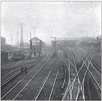
| Fig. 8. View Near Jamaica Station, Showing the Third Rail at An Interlocking Joint |
 |
| Fig. 9. Section of Third Rail and Guard |
The rail used for most of the construction has a modified tee shape and weighs 100 pounds to the yard in 33-foot lengths. The section is 4 inches high, with a head 3 inches wide, bottom flange 6 inches wide, and web 1 1/2 inches thick. This particular shape was selected because of the limited vertical distance between contact and running rail tops, requiring that the upper rail be of as low section as possible to provide maximum insulation distance to tie.
All of the main line tracks on the elevated line are provided with this too-pound third rail, excepting about 7 1/2 miles, which arc fitted with 70-pound standard relaying T-rails. For side tracking and unimportant spur work 60-pound relaying rails were used.
The contact rail is supported every 10 feet on vitrified clay insulators. Resting on top of the insulator is a malleable iron cap, which projects down over it for a distance of 1 1/8 inches and has two ears 1 1/4 inches long projecting upwards. The rail rests on top of the cap between the ears. With this type of insulator no vertical strain comes upon it due to the sagging of the tic when a train passes, as the rail is in no way directly attached to it. The design also facilitates the removal of broken insulators, as the whole device may be removed by taking out two lag screws in the base.
The third rail joints are bonded by laminated copper foot bonds with plug terminals. They vary in size according to the weight of the rail to which they are applied, 300,000, 350,000 and 400,000 c.m. sizes being employed. The holes for the plug terminals were punched in the base of the rail by hydraulic punches, and the terminals were riveted into the holes by hydraulic compressors.
CABLE JUMPER CONSTRUCTION
The third rail is frequently interrupted by highway crossings and switches, and at such places under-ground cables are provided to maintain its electrical continuity.
As at present installed the third rail system is not fed in separate sections from the sub-stations, but is treated as a continuous conductor between sub-stations, except where the number of switches and cross-overs incidental to a station terminal or junction necessitates dividing it into sections that can be easily isolated from the remainder of the third rail should emergency require. There are, therefore, no low-tension cables running along the tracks to reinforce points distant from the sub-stations, but the frequency of highway grade crossings and track switches and cross-overs requires the frequent interruption of the third rail. To maintain its electrical continuity at such places underground jumper cables are provided.
THIRD RAIL GUARD
The Stilwell-Slater type of guard was adopted for the third rail. It consists of yellow pine plank I inches thick, 7 inches wide, placed above the rail, with 2 1/2 inches clear space between the top of the rail and the under side of the plank. The edge of the plank nearest the track extends 7/8 inch beyond the line of the third rail head and is beveled back to give the necessary clearance for running equipment. Each plank has a saw cut 3/8 inch deep in the middle of the under side to prevent warping. The planks vary in length from 14 to 16 feet. The guard is supported directly from the third rail, there being four supports to each plank. The planks are butted together without splicing, so as not to interfere with the free expansion and contraction of the rail and to facilitate repairs. Fig. 9 shows the guard in detail.
All the timber guards are painted with two coats of a good quality of weatherproof paint. Experience up to the present time leads to the belief that the guard will prevent most of the troubles that commonly arise from sleet.
DRAWBRIDGE CONNECTIONS
At the drawbridges in the Jamaica Bay trestle the third rail is interrupted, and to maintain this continuity three submarine cables are installed, one for each third rail, and one extra cable. These cables consist of 2,000,000 c.m. copper core insulated with 4-32 inch of 30 per cent. Para rubber incased in a lead sheath 1/8 inch thick and armoured with one layer of No. 4 B. & S. galvanized steel wires laid on spirally with a layer of jute covering. These cables were laid in the same manner as the high-tension power transmission cables which have already been described.
The short length of third rail on the drawbridge is connected by brass contact shoes, which make connections at each end of the draw when it is closed.
SYSTEM OW THIRD RAIL CONNECTIONS
The cables connecting the third rail with the sub-stations are all of 2,000,000 c.m., and connections are made directly in front of the sub-stations. In some cases these short feeders are located in conduit and in other cases laid directly in the ground in the manner described for the crossing jumpers. Such cables when laid in ducts are insulated with 5-32 inch of paper, covered with a layer of sheathing 1/8 inch thick.
Near each sub-station the third rail is interrupted by a 40-foot gap. Should any section break down it is then impossible for a single car to bridge the gap between the live rail and the grounded one, thus avoiding the possibility of injury to the car wiring and equipment. The east and west bound tracks are in most cases supplied by a separate set of feeders and are not cross-connected except through the station bus-bars. Current can therefore be cut off from the section of either track lying between two sub-stations simply by opening the proper feeder switches in the stations at each end of the section.
In order that part of a section between two sub-stations may be disconnected in case of emergency, in-stead of requiring the whole section to be thrown out of service, 1,600-ampere disconnecting switches are installed at suitable intervals between sub-stations, being cut into the third rail circuit so that by opening any two of them the section between them can be cut out, though normally these switches are kept closed.
Practically all the line is double-tracked, excepting two stretches, which are four-tracked, one on Atlantic Avenue, between Chestnut Street and Woodhaven Junction, and the other running south from Wood-haven Junction as far as the north end of the trestle.
The only place where the east and west bound tracks are connected together occurs at the entrance to the yards, at the Rockaway Park terminal, at Jamaica Station and at the north end of Jamaica Bay trestle. At these points the two tracks are tied together by a 2000-ampere switch and circuit breaker, mounted under shelter and conveniently located, by means of which they can be separated when necessary.
Fig. 8 shows the arrangement of the third rail at a rather complicated interlocking point just east of Jamaica Station. The main third rail circuits are carried around this section by separate cables which run through a small switch house standing beside the tracks, in which is located the switch and fuse board.
RETURN CIRCUIT
Both running rails of each track are used for the return circuit. On a considerable portion of the line an automatic block signal system is used, requiring both running rails for its operation, so that a special method had to be employed in order to allow the tracks to be used jointly as a power return circuit and for signal purposes. The signal system was developed by The Union Switch & Signal Company, of Swissvale, Pa., and employs alternating current for the operation of the signals. With the aid of a special arrangement of bonding, the track is used for carrying both direct and alternating current without the former affecting the latter.
Where the automatic block signal system is used it is not possible to cross bond the pinning rails on ac-count of the disturbance in the signal system which would thereby result. The cross connections only occur at the end of the signal blocks, where the special inductive bonds are cut into each track rail. These inductive bonds serve to keep out signal current, but for the direct cur-rent act exactly the same as the ordinary bond and maintain the continuity of the running rail. The cross connections between the tracks are made at these points, the inductive bonds being used in both tracks, so that the signal system is not affected by the flow of current between them.
The feeder connections between the track rail and the negative bus bar connections in the sub-stations are 2,000,000 c.m. bare tinned copper cable. In some cases these cables are buried directly in the ground without protection, while at others they run in vitrified clay ducts.
SUBSTATIONS
The principal feature of each sub-station is its equipment of rotary converters and transformers. In a single instance, namely, at Hammel, a storage battery was installed as an adjunct to the sub-station machinery. The location and arrangement of all the sub-station buildings is such as to enable the ultimate use of a storage battery should future conditions justify it, and the apparatus in each building is so laid out that if the storage battery should be installed the necessary boosters can occupy the space allotted to one rotary converter.
The sub-station equipment also includes two portable sub-stations, each consisting of a car containing one 1000-KW. rotary converter, three 375-KW. transformers, and the necessary blower and switchboard panels, high-tension oil circuit breaker, and connecting leads to the outside circuit breakers.
A storage battery was installed at Hammel, which is further from the power station than any of the other sub-stations, and, by reason of the exposed position of the transmission line running across Jamaica Bay, might be considered somewhat more liable to interruption in service through accident to the transmission. The marked fluctuations in load at this point, due to heavy travel to Rockaway Beach on summer afternoons and evenings, afford a better opportunity than almost any other location for testing the general applicability of the battery. The fact that the station load in the winter time is extremely light enables it to be operated for much of the time at this season from the battery alone, with the minimum cost of sub-station attendance during the greater part of the year. The storage battery equipment consists of 300 cells of 3200 ampere-hours capacity, and two boosters of 162-KW. capacity each.
SUB-STATION BUILDINGS
The buildings vary in height, due to the presence of overhead high-tension circuits. Where underground circuits only are used, as is the case at East New York and at Hammel, there are but two floors in the high-tension gallery. At Woodhaven and Rockaway Junction, however, where overhead circuits are employed, a third story is added to the high-tension gallery, which serves the double purpose of affording a convenient entrance to the building for the cables, about on a level with the cross-arms, and at the same time provides a suitable chamber for enclosing the high-tension lightning arrester apparatus.
Each sub-station is served by a 16-ton Niles crane, hand operated from its trolley, thus obviating the usual hanging chains. It spans the central bay and is available not only for handling the permanent heavy sub-station machinery, but also the apparatus of the portable sub-stations which, excepting at Grand Avenue, can be run under it upon a track that enters one of the end-bays of the building.
 |
| Fig. 10. Sectional Elevation of the Sub-Station at Woodhaven Junction |
| |||
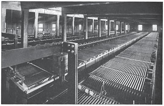
| Fig. 11. in the Sub-Station at Hammel, 300 Cells of 3200 Ampere-Hours Capacity Are Installed With Two 162-Kw. Boosters to Take Care of the Load Fluctuations on the Rockaway Beach Line. |
| |||
| Fig. 12. An Interior View of Part of the Sub-Station at Woodhaven Junction Looking Toward the High-Tension Gallery |
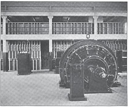
Fig. 10 shows a complete sectional elevation of the sub-station at Wood-haven Junction, and Fig. 12 is an interior view of this station looking to-ward the high-tension gallery. The building is provided with a track entrance for the portable sub-station. It stands on railway property of sufficient size to accommodate a battery house immediately in its rear, should one ever become necessary.
ROTARY CONVERTERS
The rotary converters are of the two-bearing type, with field frames divided in a horizontal plane. Each converter is provided with a starting motor, whose frame is mounted upon an extension of the base of the rotary converter. The base frame is set into the floor so that the top of it is level with the floor line. It is entirely open below the commutator so that there is easy access to the lower brushes from the pit in the interior of the foundation, which can be easily reached from the basement.
The 1000-KW. rotaries, three of which are installed in the sub-stations at Grand Avenue and at East New York, and two at Rockaway Junction and at Hammel, are rated to deliver 1600 amperes at 625 volts, and 1667 amperes at 600 volts. The three-phase potential at the alternating-current end is approximately 370 volts, for 625 volts at the direct-current end. These machines have eight poles and operate at 375 revolutions per minute, corresponding to a frequency of 25 cycles per second.
The three 1500-KW. rotaries at Woodhaven Junction are rated to deliver 2400 amperes at 625 volts, or 2500 amperes at 600 volts. They have twelve poles and run at 250 revolutions per minute.
In nearly all respects the two sizes of machine are very similar. The fields are compound wound with the shunt winding arranged for self-excitation. The machines are so over-compounded, that if operated as direct-current generators at constant speed, the voltage will rise from 600 volts at no load to 650 at full load. The laminated steel pole pieces are beveled at the edges, and slotted through the faces to allow the use of massive copper dampers of the grid-iron type, which pass through and around the pole faces. The synchronizing power is thereby in-creased and hunting prevented.
TRANSFORMERS
The transformers used with the converters are of the air-blast type throughout. Those for the 1000-KW. rotary converters are grouped in banks of three 375-KW. transformers to one rotary converter. For the 1500-KW. converters they are in groups of three 550 KW. each.
The high-tension winding is de-signed for a normal electromotive force of 12,000 volts with taps arranged to enable other voltages to be utilized down to 10,000 volts. The low-tension winding is designed to normally carry 400 volts with taps which will enable other voltages to be taken off it down to 340 volts.
AUXILIARY TRANSFORMERS
In each station there are four sets of auxiliary transformers which supply current for the following purposes:-
1. To the rotary converter starting motors.
2. To the motors driving the booster generators and their exciters. At Hammel station these transformers are made large enough to also drive rotary starting motors at the same time.
3. For driving the transformer blower motors, and an induction motor-generator set used to charge the small auxiliary storage battery that supplies current for the electric switch control system.
4. For house lighting.
HIGH-TENSION BUS-BARS AND CIRCUIT BREAKERS
The sectional elevation at Wood-haven Junction sub-station, Fig. 10, shows the high-tension cables entering through the lightning arrester gallery in the third story. The cables extend down the wall into the basement and run first to the proper oil switch, and thence up to the transfer bus in the gallery overhead, each cable being in a separate brick septum. The outgoing branch circuits are tapped out of the transfer bus, each tap coming down a septum in the back wall of the bus structure to the oil switch directly underneath.
Between every oil switch and the bus to which it is connected is a set of three disconnecting knife switches, one in each phase. Their function is to completely isolate the circuit breaker from the bus-bars, and to facilitate inspection, cleaning and re-pairs. Two of the outgoing branch circuits emerge underground, while the third leaves by the overhead route.
HIGH-TENSION SWITCHES
The switches for manipulating the 12,000-volt current for the feeders, and for the leads to the main trans-formers, are Westinghouse oil circuit breakers.
They are all three-pole, with two stationary contacts per pole, one for the incoming and the other for the outgoing lead of the same phase. Each pole of the oil circuit breaker is enclosed in a separate fireproof chamber of brick, capped with a slab of alberene stone upon which the operating gear is mounted.
Both automatic and non-automatic circuit breakers are employed. They are all automatic except those used for connecting the sections of the transfer bus, and for connecting the two transfer buses to the rotary bus. The switches controlling feeders that pass through a station, and also those which control apparatus supplied from the rotary bus, are all automatic.
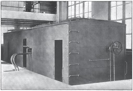
PORTABLE SUB-STATIONS
Two portable sub-stations were provided, each consisting of a 1000-KW. rotary converter with trans-formers, switchboard apparatus and the necessary auxiliaries, carried in a heavy steel car resembling a freight car in general appearance. A sectional elevation of this sub-station car is given in Fig. 13, which shows the disposition of the apparatus.
 |
| Fig. 13. Sectional Elevation of A Sub-Station Car, Showing Arrangement of the Equipment |
| |||
| Fig. 14. A Sub-Station Car Connected Up in the Interior of A Permanent Sub-Station. the Car is Built of Steel and Resembles A Freight Car in Appearance |
The end of the car containing the rotary converter is so built that it can be readily taken to pieces, and in fact, entirely knocked down so that the rotary converter can be easily taken apart if necessary, by being run under the crane in any of the sub-stations.
Besides the rotary converter, which is identical with the previously de-scribed standard rotary converters of 1000-KW. capacity, are three 375-KW. transformers of the air-blast type, fitted with blower and motor. The apparatus can perhaps be best described by following the course of the current through it.
The high-tension connections enter through an opening in one end of the car, which, when not in use, is closed by a steel flap hinged so as to fall directly over the aperture. The three connections for the three-phase current are tapped directly to lugs that project through the rear of the oil switch structure. The oil switch is of boo amperes capacity, three pole, and electrically operated. Just before entering the oil switch, taps are taken off for two potential trans-formers, both of them being used for the wattmeter connections, and one of them being used as the line side of the synchronizing apparatus.
After leaving the oil switch, the main connections pass through series transformers, from which run connections for the integrating watt-meter. The main connections then run directly to the main trans-formers, where they fasten to the terminals of the high-tension coils. On the low-tension side of the main transformers, four connections are made between each transformer and a transformer terminal panel. These four taps are arranged so as to give four different voltages for the rotary converter, as on such a large system as this it is quite likely that the volt-age at different sub-station points may vary from time to time under different conditions. This trans-former terminal panel is provided with several switches making possible four combinations of voltage. The main alternating connections then run directly to the alternating-current rotary converter panel through heavy bus-bars extending up past the top of the panels. On the main alternating-current panel, taps are taken off for the rotary starting motor, and also for the synchronizing transformer on the machine side. From this panel the main cables run direct to the alternating-current side of the rotary converter.
The portable sub-station rotaries are synchronized from the low-tension side, by means of a synchroscope. That is, the rotary converter is started up by the starting motor after the transformers have been cut in, and by the aid of a synchroscope the low-tension alternating-current switches on the rotary panel are thrown in by hand at the instant of synchronism.
From the direct-current side of the rotary, the negative connection runs direct to a lug, mounted on a slab, placed conveniently at the side of the car. opposite the opening, through which connections are made to the fixed lugs in either the portable sub-station house or in the permanent sub-station. There is no switch in this connection. The equalizer is also taken from the negative pole of the machine and run to an equalizer switch mounted on the inside of the car, conveniently to the slab supporting the outgoing lugs, whence a connection can be made to the other portable sub-station if it is in the same house, or to the equalizer bus of the permanent sub-station if that is where the portable sub-station hap-pens to be working.
The positive leg goes to a direct-current panel in the car, which carries a single 2000-ampere switch, with 3000-ampere ammeter and circuit breaker. From the circuit breaker a connection is led to the slab where the taps are made to whatever third-rail circuits the port-able sub-station is connected. Fig. 14 shows one of the portable sub-station cars connected up in the interior of a permanent sub-station.
SUB-STATION HEATING AND LIGHTING EQUIPMENTS
Each sub-station is fitted with a hot-water heating system supplied from a boiler in the basement. The lighting is accomplished through a transformer which supplies a 105-volt three-wire lighting bus. Ten lighting circuits are distributed from fuse slabs carried on the back of a separate marble panel, and there are ten switches for the accommodation of the various lighting circuits that run about the building. Both 16-candle-power incandescent lamps and 4-glower Nernst lamps are used.
TRANSFORMER BLOWER OUTFIT
As the main transformers in these sub-stations are all of the air-blast type, electric driven blowers are provided to furnish the necessary draft. They are in two sizes, and are operated at 480 revolutions per minute by motors of 9.8 H. P. and 6.6 H. P., respectively. The motors are coupled direct to the fans, and are of the three-phase induction type operating at 400 volts from auxiliary trans-formers.
SIGNAL SERVICE APPARATUS
The railroad lines are protected by a block signal system specially devised to work with alternating cur-rent, by which means it becomes possible to make use of the well-known feature of short circuiting the two rails of the track without requiring that one of them shall be devoted only to signaling purposes, which would cut down by one-half the capacity of the track return circuit.
Accordingly, a set of transformers is placed in the Woodhaven Junction sub-station, there being two of 100 KW. each, one only being in service, the other being a spare set. These take 11,000-volt current, single-phase, and transform it to 2200-volt current for use in the signal system. The transformers are located in the basement and are supplied through a type B, 11,000-volt oil switch mounted on a separate marble panel.
AIR CLEANING SETS
At each sub-station there is provided a motor-driven air compressor, the motors of which are wound for 600 volts, direct current. Their capacity is 60 cubic feet of free air per minute, up to 100 pounds pressure. The motor is geared to the compressor. The compressor supplies a system of air piping running to outlets conveniently placed for blowing air into the rotary converters and the switching apparatus for cleaning.
CONCLUSION
The completed overhead line was first put in service April 27, 1905, and the third rail was first put in service about May 13, 1905. Regular operation began July 26, 1905.
The sub-stations were first sup-plied with high-tension current from the overhead lines, and tested out on April 27, 1905. Current was first furnished from Woodhaven Junction to the third rail for car tests May 13, 1905. The portable sub-stations were first placed in operation June 12, 1905.
The operation of the transmission line and the third rail have been remarkably free from interruption of any kind, and has demonstrated their efficiency as a substantial and reliable transmission system for a suburban railroad, on whose regularity of operation thousands of people are daily dependent.
The design and construction of the entire transmission and sub-station system were carried out by Westinghouse, Church, Kerr & Company, engineers for the Long Island Railroad Company, and the entire work was under the direction of Mr. George Gibbs, chief engineer of electric traction of the Long Island Railroad, subject to the approval of an electric committee consisting of the chief operating officials of the road, with the president as chairman.
