[Trade Journal]
Publication: Electric Railway Review
Chicago, IL, United States
vol. 19, no. 6, p. 174-176, col. 1-2
CATENARY CONSTRUCTION ON THE SYRACUSE LAKE
SHORE & NORTHERN RAILROAD.
The Syracuse Lake Shore & Northern Railroad on January 25 placed a 4 1/2-mile stretch of catenary construction designed for single-phase current at 6,600 volts in operation. using direct current at 550 volts.
The road is at present about 12 miles long and cars are operated on a half-hour schedule from Syracuse to Baldwinsville, N. Y. As originally built the line was single track. following a circuitous route. When in September, 1905, the property was acquired by the present interests, the work of entirely rebuilding the road was undertaken. and this has included a second track, much of which has already been completed, as well as the relocation of the portion now equipped with catenary trolley construction. The road is to he extended from Baldwinsville, through Phoenix and Fulton to Oswego, making a line about 30 miles long. Much of the distance from Baldwinsville to Fulton is already graded.
| |||
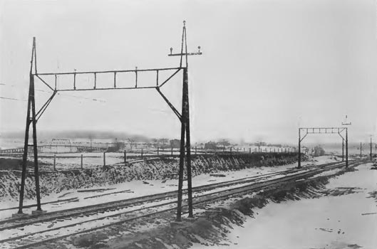
| Syracuse Lake Shore & Northern Railroad — Catenary Trolley Construction and Power Transmission Line. |
Catenary Bridges.
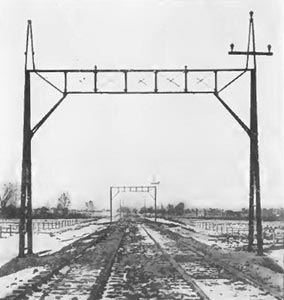
The catenary work, as previously stated, Is designed for single-phase at 6,600 volts. but owing to the facts that but a small portion of the proposed work has thus far been completed and that the rolling stock is built for direct current, the road is being operated under the alternating-current-direct-current system. As will be seen from the accompanying engravings a single messenger cable is used with steel bridge construction. The bridges are located 200 feet apart on tangent and have a span of 30 feet. the track being laid on 12-foot cotters. The bents for the bridges are built of two 2-inch channel members, spaced 6 feet apart at the base. converging to 8 inches at the top and supported on concrete pedestals 20 Inches square and of varying depth according to the nature of the ground. The trusses have 6-inch channel top chords and 6-inch channel bottom chords set flanges down, the diagonal members being 5/8-inch rods and the struts 2 1/2 by 2 1/2 by 1/4 inch angles. The struts are flattened and bent over at the ends and riveted to the channels. Malleable iron pins for the porcelain insulators carrying the messenger cable are bolted to the top chord of the truss.
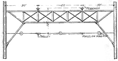 |
| Syracuse Lake Shore & Northern Railroad — Plan of Steady Attachment at Catenary Bridges. |
The messenger cable is 7/16-inch galvanized cable, furnished by the John S. Roebling's Sons Company and No. 0000 grooved copper wire, furnished by the same company, is used for the trolley wire. The trolley hangers are galvanized steel rods 3/4 inch in diameter, spaced 10 feet centers. These hangers are of the Ohio Brass Company's standard type, attached to the messenger cable with a sister hook, through the base of which the rod is threaded and drawn up tight against the messenger cable. The trolley wire is secured to the hanger by mechanical ears.
The catenary is strung for a net sag of 6 feet 6 inches at 100 degrees F. At 20 degrees F. the sag is about 5 feet 6 inches and the trolley is 12 inches higher at the center of the span than under the bridges, the height from rail to trolley being 18 feet. The bridge construction is designed for a wind pressure of 8 pounds per square foot on the trolley and messenger cables when covered with 1/2 inch of ice. A somewhat lower load is assumed on the high-tension wires, which are No. 2 copper. Under the assumed wind and ice load the unit strain on the bridge is 22,500 pounds per square inch. reduced for the compression members of the bridge, which is computed as a braced portal.
At each bridge there is a steady strain attachment applied to the trolley in the manner Indicated by an accompanying plan, the Ohio Brass Company's 8-inch wheel type insulators being used. The messenger cable is dead-ended on an equalizer attached to a pair of these insulators, which are in turn connected by short cable loops secured to the anchor bridge. Temporarily the dead-end bridges are the same as the other bridges along the line with the addition of a second channel top chord set at right angles to the other channel chords and to which the catenary dead end is bolted.
During the 10 days the catenary work has been in service there have been temperature changes of 50 degrees and wind velocities of 45 miles per hour. These conditions have appeared to make no difference in operation, even before the steady strains were Installed, and the lateral stiffness has been such at all times that very little deflection or roiling can be noticed under the action of the wheel trolley with a tension about 25 pounds.
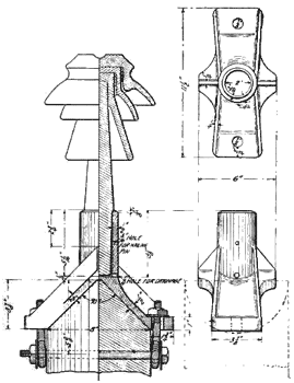 |
| Syracuse Lake Shore & Northern Railroad — Standard Socket for Pole-Top High-Tension Line. |
As will he seen from the engraving the construction is comparatively simple, and though in operation for but a short time has been very satisfactory, there having been no trouble from trolley wheels jumping the trolley wire. The construction also gives to the motorman all along his range of vision a clear view or both sides of the right of way, and it is believed will be permanent and much more satisfactory than a catenary bracket construction using wood poles. In this connection It is interesting to note that as compared with the standard span construction for double track using 35-foot cedar poles 8 inches in diameter at the top and spaced 85 feet apart the cost for the catenary construction of the type described has been hut $800 per mile greater. The catenary work was designed by the Archbold-Brady Company of Syracuse. This company also designed and furnished the steel catenary bridges and designed such special work as was required, all of which was subject to the approval of Thomas H. Mather, chief engineer of the Syracuse Lake Shore & Northern. All catenary clips, hangers and insulators were furnished by the Ohio Brass Company. The work of erection was done under the immediate direction of L. J. Myers, superintendent of construction of the road.
| |||
| Syracuse Lake Shore & Northern Railroad — Partially Completed Catenary Trolley Construction and Power Transmission Line. |
Power Transmission Lines.
The three-phase power transmission line is carried on an A-frame on the catenary bridges throughout the length of the catenary construction, power being obtained from an auto-transformer station of the Niagara Lockport & Ontario Power Company, located on the outskirts of Baldwinsville, which delivers current at 22,000 volts. On the portion of the line between Syracuse and Long Branch, which has the standard suspension overhead work with wooden poles at the side of the right of way, the transmission line is carried on the pole tops. A special bracket designed for the insulator pin immediately on the top of the pole and shown in an accompanying engraving is used with a 6-foot crossarm below. The power transmission line runs to the power house of the Syracuse Lake Shore & Northern at Nine-Mile creek, about 4 1/2 miles from Syracuse, where the current is at present stepped down to 402 volts and a 500-kilowatt rotary converter used to furnish the necessary direct current for present operation. The company also has here its two engine-driven generators, used heretofore as reserve for emergency. The new equipment was all furnished by the Westinghouse Electric & Manufacturing Company. The switchboard equipment includes integrating and recording wattmeter automatic synchronizer and all the essential apparatus for the operation of the power equipment.
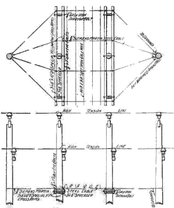 |
| Syracuse Lake Shore & Northern Railroad — Cradle Construction for Protection of Steam Railroad Crossing and Power Transmission Line. |
Roadbed.
The double-track roadbed is at present on cinder fill, cinders being obtained in large quantities from the Solvay Process Company. When these become thoroughly packed they afford a good subconstruction for crushed rock ballast. The rails are 70-pound sections. They are bonded with Chase-Shawmut soldered bonds.

