[Trade Journal]
Publication: The Journal of Electricity, Power and Gas
San Francisco, CA, United States
vol. 11, no. 1, p. 8-25, col. 1-2
WASHINGTON'S GREATEST TRANSMISSION
BY ROBERT McF. DOBLE.
UNQUESTIONABLY the Pacific Coast leads the engineering dynamos to produce electric energy for transmission to distant markets. The building of such "transmissions," as they are termed, is no longer looked upon as an experiment, and the large number of such enterprises in successful operation, both technically and financially, prove their practicality and commercial value and explain why many more and bolder tranmissions are under construction or are being undertaken. Of the completed and operating plants one of the most important and interesting is that of the Snoqualmie Falls Power Company, located in the state of Washington.
The Snoqualmie transmission is extremely interesting on account of its several novel features and constructive details, the most notable being the subterranean generating station and the use of aluminum wire for the transmission lines. It is an enterprise of vast proportions and involved much labor and the overcoming of many difficulties in its successful execution; and as for the market, the rapid and substantial growth of the centers of population and commerce to which its power is furnished guarantees a steadily increasing demand for its output, the cheapness and abundance of which is a material aid in still further building up the cities so fortunately situated as to profit by it.
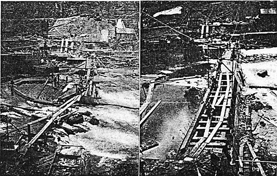
| |||
| The Dam During Construction. Showing Trolley and Loaded Tray. |
The great fall of the Snoqualmie River is situated about twenty-five miles easterly from Seattle, in the foothills of the Cascade range, on the line of the Seattle and International Railway. With its vertical drop of 270 feet, exceeding the Niagara Falls by more than 100 feet, it has long been famous for its impressive grandeur and the scenic beauties of its surroundings. From a heavily timbered water-shed of above 500 square miles in area on the westerly slope of the Cascade Mountains, and reaching an altitude of over 8000 feet, flow the three principal tributaries of the Snoqualmie River, designated the north, middle and south forks respectively, and which unite about three miles above the falls, forming the river proper.
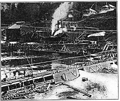
| |||
| The Dam During Construction. |
The water-shed area contains many beautiful mountain lakes and other available sites which may be utilized as storage reservoirs when the present generating plant may have been more than doubled and the demand for power may exceed the natural flow of the river during the summer months. The river has a large low-water flow during the usual dry months, being kept up by the tributaries which reach above the snow line. As to rainfall, that on the upper head waters is said to exceed 150 inches per annum, while at the falls the total precipitation is about go inches and at Seattle only about 35 inches.
The water of the river usually is pure and clear but carries considerable sand and fine, sharp silt during and after the freshets. These occur generally in November, owing to the heavy rainfall, and during June, owing to the melting snows. The water level fluctuates considerably throughout the year with occasional freshets caused by rain, the minimum flow at the falls being about 1000 cubic feet per second and the maximum over 10,000.
| |||
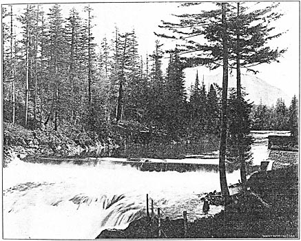
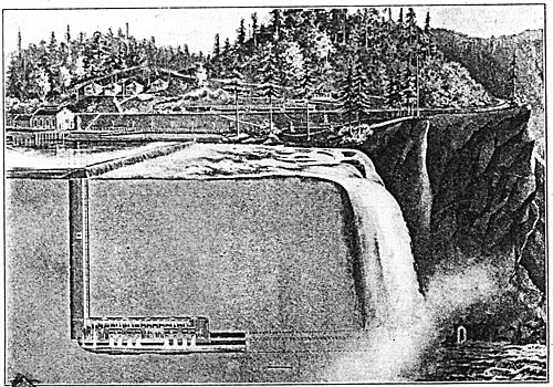
| The Dam After Construction. |
About one-quarter of a mile above the falls, where a uniform cross-section of the river exists, a gaging station was established and an exhaustive series of readings were taken of the height of the river as well as current meter observations. The average velocity obtained was about ten feet per second and a daily record is still being kept of the stage of the river at morning and evening. The river does not freeze during the winter and there is neither floating ice nor anchor ice to be dealt with. The crest of the falls is about 600 feet above the sea level. Below the falls the Snoqualmie River runs almost due north until it makes a junction with the Skykomish River, the two forming the Snohomish River which flows into Puget Sound near the city of Everett.
The rock at the falls is basaltic, with no regular cleavage, is hard and nonabsorbent and apparently is divided into great ledges by seams. These conditions led to the adoption of the scheme of placing the entire generating plant in an underground chamber, thus avoiding the necessity of having a long flume or pipe line as is usually required. The location of the power house on the river bank at the base of the falls was considered, but on account of the clouds of spray which keep everything damp and in winter freeze and coat everything with ice, it finally was decided to excavate a chamber in the solid rock.
HYDRAULIC DEVELOPMENT.
The water is taken direct from the river into the intake, a massive concrete and steel construction, about 6o feet along the river. It is built upon the solid rock formation of the river bed, with wails six feet thick and 25 feet high. To keep out floating logs and trees the front of the intake is protected by a timber grating supported by a steel girder frame built into the concrete. The timbers are 12x12 inches laid horizontally with 12-inch spaces between them.
The forebay thus formed is divided into two headbays, separated by a concrete wall six feet thick, both equipped with a massive timber bulkhead and headgate, having an opening 8x12 feet through which the water flows to the penstocks. The headgates are operated by double-screw stems with worm-gear nuts and worm mechanism with large hand-wheels but may also be operated by an electric motor. Only one headbay is in use at present, the other haying been provided for doubling the present generating capacity of the plant.
The active headbay is further protected by a screen made of flat steel bars on edge which serve to screen out the leaves and other small debris. The timber grating is further protected from floating logs by a floating fender in the form of a rudder boom 300 feet long, which is moored above the intake and extends past it. By turning the capstan at the head of the boom the rudders are thrown out and the boom may be swung into any desired position diagonally across the river. At this point the river is about 150 feet wide and 15 feet deep at low water.
For a distance of about 400 feet up stream and for about 200 feet down stream from the intake, the river banks have been brought to line and protected by massive timber bulkheads constructed of sawed cedar 12x12 inches laid horizontally. The bottom courses are solidly anchored to the bedrock by means of iron bolts, each course being secured to the under one by a liberal number of drift bolts, and every other course being tied back into the solid bank by long 12x12-inch cedar ties solidly anchored. The upper five courses are stepped back eight inches each.
At one place in the upper bulkhead where there was a deep hole under a portion of the bottom timber, steel rails and sheet piling were driven into the stiff clay and securely bolted to the upper structure, and the enclosed area behind the bulkhead was also driven with nests of steel rails and the whole filled with large pieces of rock and tied well back to the solid embankment. Extra precautions were taken with all of the river embankment and intake work as the river is torrential in character and at freshets brings down logs and whole trees of enormous size which would prove disastrous to any construction not of the most massive variety and properly planned to resist such conditions.
For the purpose of raising the low-water elevation of the river at the top of the penstock to a depth of a minimum of eight feet a dam was constructed across the river about 200 feet below the intake and about 200 feet above the crest of the falls. This is a submerged concrete and timber construction about 218 feet between the piers, varying in height from three feet to ten feet, with a level crest eight feet wide, with a slope on the up-stream side of two to one and on the down-stream side of one-half to one, varying in width on the rock bottom of the river from 16 feet to 35 feet. At each end of the dam is an abutment pier eight feet square and five feet in height above the crest of the dam. This elevation is also that of the lower bulkhead, which below the dam is continued in the form of a heavy concrete retaining wall, with an outside batter of one-half to one. Thus is formed a spillway over which the water freely flows whenever it exceeds a depth of five feet over the crest of the darn, and allows for the discharge of flood waters without unduly raising the surface of the river above the dam.
To insure a firm bond between the bottom of the dam and the river bed, the rock was laid bare by the use of cofferdams and then roughened up and studded with pieces of steel rails driven into drill holes about two feet deep in the bedrock and also projecting up into the concrete structure from three feet to five feet.
The dam was built during the time of usual low water and work was going on at both ends and in the middle at the same time, the flow of the river being diverted from one place to another, finally being forced through sluiceways which at the last were closed in with timbers and concrete with over a foot of water flowing over the finished portions of the structure.
After the bottom of the river had been made available, a framework and sides were solidly constructed of 6x12-inch timbers, well braced, and this structure was then filled with good Portland concrete and capped over with 6x12-inch timber. The work was handled expeditiously as the stage of the river always is uncertain and twice during the construction the portions completed were completely submerged by freshets. Use was made of an overhead cable one inch in diameter and 500 feet long with a traveler operated by an engine located on the south bank of the river. By this means the timbers, concrete and other materials were rapidly carried to the places desired. The rock was broken by a crusher but the concrete was mixed by hand. Owing to the slope of the banks on both sides of the river the concrete mixing was done on platforms one above another, each process separately, and the ingredients then being passed along to the next through chutes.
THE SUBTERRANEAN POWER HOUSE.
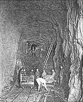
About 300 feet above the falls, a shaft 10x27 feet was sunk in the bed of the river on the south side, descending 270 feet to the level of the river below the falls. While this shaft was being excavated, a tunnel 12 feet wide and 24 feet high, with a fall of two feet in its entire length, was drifted in from the face of the ledge below the falls, to an intersection with the bottom of the shaft, a distance of 650 feet.
| |||
| Frozen Spray at Mouth of Tailrace. |
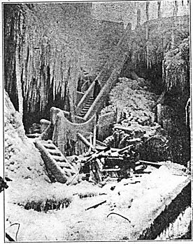
Beginning at the foot of the shaft and extending over and along the tunnel, a chamber 200 feet in length, 40 feet wide and 30 feet high, with the floor at the elevation of high water below the falls, was excavated out of the solid rock. This, chamber forms the power house or machinery room in which the water wheels and electric generators have been installed At average stages of the river the water is about 12 feet deep in the tunnel, while during flood seasons it nearly fills the tunnel. The tunnel extends under the floor of the chamber, forming a tailrace with a concrete roof five feet thick. The walls of the chamber have been left rough and whitewashed, while the floor is covered with concrete.
About 700 incandescent lamps are used to light the shaft, chamber and tunnel. The chamber is ventilated by natural draft through the tailrace and up the shaft, the draft being so strong that it has to he curbed. The chamber is cool and perfectly dry, the temperature remaining the same (about 55° F.) throughout the year. This low and uniform temperature contributes to high efficiency of the generators.
| |||
| Cross-Section of Subterranean Generating Station, Tailrace Tunnel, Falls, Etc. |
The shaft is 10X27 feet, and at the top has three compartments; the two end compartments are for the penstocks, while the center one, enclosed at the top by a steel bulkhead, forms a shaft 8x10 feet for the hydraulic elevator and the main cables forming the outgoing conductors, and also for raising and lowering machinery, etc. The steel bulkhead which encloses this center shaft extends from the bottom of the intake bay to the surface of the ground. It is built up of steel plates, and is stiffened by horizontal frames of I-beams on the outside, riveted to the plates and to each other at the ends. Below it, the elevator shaft is timbered and sheathed with plank. At the surface, this shaft is surmounted by a small building. The penstock already built is a steel pipe 7 1/2 feet in diameter, passing through a concrete roof which keeps the shaft watertight. The plates are in eight-foot courses, and are one inch thick for the lower half of the pipe; in the upper half, the thickness decreases from 7/8-inch to 1/2-inch at the top. The joints are heavily rived and caulked watertight. At a depth of 250 feet the penstock reaches the chamber and connects with a horizontal cylindrical receiver which rests on a rock bench in the north side of the chamber, 12 feet above the floor. This receiver extends almost the full length of the chamber. Its diameter is so feet for half its length, and then reduces to eight feet. It is built up of one-inch plates, eight feet wide. The penstock and receiver weigh 225 tons, and the weight of the water column in the penstock is 340 tons. A small independent penstock supplies water to the elevator machinery.
THE MAIN HYDRAULIC PLANT.
The hydraulic part of the plant is very interesting, embodying as it does several features that are novel, and designed especially for this plant. The main wheel units are the largest and most powerful tangential wheels thus far attempted under similar head, and the order given for their construction is the largest single order ever given for wheels of their type.
In considering this work in detail, it will be subdivided into two divisions; first, the main power generating wheel sets; second, the auxiliaries consisting of the exciter and elevator operating gear.
In the cavity are installed four wheel units, each developing 2500 horsepower and being direct-connected to its generator. These units are of the tangential ellipsoidal type, as described in detail in THE JOURNAL for October, 1899 (Vol. VIII, p. 85, et seq). In considering the units in detail it will be well to follow the course of the water in its passage from the receiver or enlarged horizontal pipe, that is placed on the shelf of basalt, until it is discharged into the tailrace. The several drawings showing the different views of the apparatus will make the written description snore easily followed. The following description is of one unit, which applies to all four as they are similar in detail:
| |||
| Elevation and Section of Water Motors. |
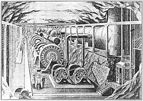
 |
| The Underground Machinery Chamber As Sketched by An Artist. |
The receiver has four supply openings which are controlled by individual double-screw gate valves of 48 inches inside diameter and weighing 23,000 pounds each. This receiver is horizontal, and the openings are on its side and open towards the cavity. These valves are said to be the largest in the world operated under such pressure. Each is fitted with a small by-pass.
Bolted direct to the gate valve is an elbow casting that directs the water directly downward into the distributing receiver. This elbow is 48 inches inside diameter. The metal is two inches thick and weighs 8000 pounds. Owing to the large diameter of this casting and its form, it required special care in its design to avoid internal strains in the casting that might lead to rupture, especially when considering the high pressure it is required to withstand. The elbow casting was tested to 200 pounds per square inch hydrostatic pressure, and test pieces attached to the casting gave over 41,000 pounds per square inch ultimate tensile strength.
The elbow is bolted directly to the flanged opening of the distributing receiver. The water enters the distributing receiver, flowing ill a downward direction, and without changing this general direction is discharged from the six openings along the bottom into the six multiple nozzles that direct and regulate the water that is applied to the wheels.
| |||
| Interior of the Receiver. |
The distributing receiver is 48 inches inside diameter and 20 feet 8 inches in length; is made of tested marine steel plates one-half inch thick, with dished heads. Stay-bolts are used to compensate for the metal removed for the forty-eight-inch opening in the top. The shell is made of two plates ten feet wide, and of a length sufficient to make the shell with only one longitudinal seam, which is double riveted. Flanges and nozzles a re cast of semi-steel. By using the distributing receiver to distribute the water to the wheel nozzles simplified the design of the plant, with the minimum of space occupied and with the least disturbances set up in the water, and therefore a minimum friction loss in the water.
| |||
| Erecting Nozzles and Manifolds. - Units I and II. |
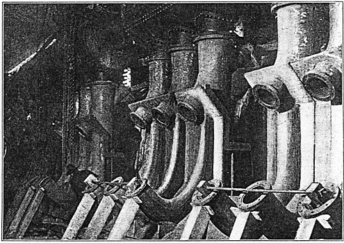
T h e distributing receiver is directly over and is supported by the six regulating nozzles standing upright upon the foundation, an d the water is discharged from the distributing receiver without any change in direction, into the nozzles. To make the path of the water as straight and free from any change in direction as possible, and of a uniform velocity of flow, was carefully considered throughout the entire design. The nozzles stand upright on the foundation, and the extreme or lower end is curved so as to direct the water upward against the wheel; the end of the nozzle terminating in a tip.
Each nozzle has two tips, each tip discharging a jet of 3 7/8 inches nozzles. The first tip is at the upper end of the nozzle and discharges the water in a downward direction against the wheel.
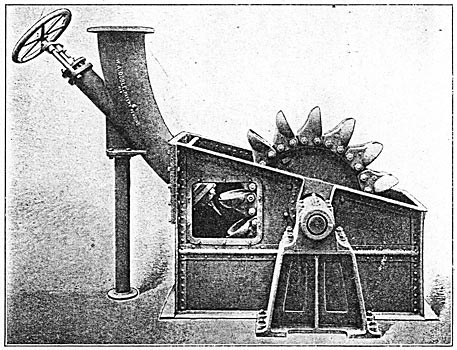
 |
| One of the Water Wheels Used on the 2500-Horsepower Units. |
To handle the volume of water necessary to develop the power in each unit under the head of 225 feet, required twelve jets, each 3 7/8 inches in diameter, discharging against six wheels. For convenience of bearing and shaft design these wheels were divided into two groups of three wheels each; each group being in a separate housing with a bearing between. This arrangement made two groups of three nozzles each, and as the nozzles were to be in an upright position, for stability each nozzle had wings cast on each side, of the proper length, and flanged so that when these flanges were bolted together it made the nozzles the proper distance apart, and the wings formed the back of the housing or casing in which the wheels revolve, as well as making a most stable construction.
| |||
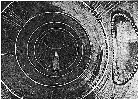
| A Flashlight Photograph of the Regulating Nozzle and Exciter Wheel in Action. |
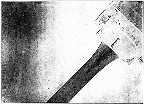
One of the new features of this plant is the regulating tips that are used on the nozzles. They not only throw a perfect and unbroken stream, which can be seen front the above photograph (which is of a three-inch nozzle, 253 feet head, partially closed so as to throw a stream 2 1/4 inches in diameter), but give an absolute control over the quantity of water applied to the wheels; therefore over the power output of the unit. As the nozzles are controlled by the governor, they give a perfect speed regulation with variable load at a high efficiency, and with the utmost economy in the consumption of water. This photograph is by flashlight, and was taken from one of the exciter wheels at the Snoqualmie plant. It clearly shows a solid, transparent, smooth stream, entirely free from any swirling or other disturbances; in fact an ideal stream condition to deliver the greatest power to the wheels; this form of nozzle maintaining this same condition from full jet to one-tenth of the jet area.
 |
| Front and Rear Views of Main Nozzle Castings. |
The regulating nozzles are operated from two long rocker-shafts by means of cranks and connections. One rocker-shaft controls the upper, and the second rocker-shaft controls the lower nozzle tips. Both rocker-shafts are operated by a water-wheel governor which is connected by cranks and connections. The connections to each rocker-shaft are so arranged with clutches that either or both rocker-shafts can he disconnected from the governor and operated or regulated by the hand-wheel on the pedestal stand. By this governor arrangement, with the regulating nozzle tips, the wheels use water in proportion to the power developed, so that the wheels are of very high efficiency at part load as well as at full load. The six wheels have split hubs and solid ribs, and are a press fit on the nine-inch shaft. The wheel hubs are held with four steel bolts 1 3/4 inches diameter, and the wheels rotate the shaft by means of a steel feather let into the shaft. The wheels are 45 inches in diameter, and are provided with buckets of the ellipsoidal type. The 13 buckets used are attached to the wheel rim by fitted bolts so that the buckets can he replaced when they become worn front scour or otherwise deranged. This is an advantage over wheels of the turbine type where the buckets are part of the wheel casting, and if worn or damaged require the replacing of the entire wheel. The six wheels are keyed on the shaft in two groups of three wheels each. The shaft is forged steel 9 inches in diameter and 24 feet 5 inches long. On one end of the shaft is a heavy flange coupling which is bolted solid to the coupling on the generator shaft with fitted bolts.
The shaft is supported in two bearings of the ring-oiling, removable shell type. One bearing is at the extreme end of the shaft and the second in the middle of the shaft length and between the two wheel housings. The generator bearing carries the other end of the shaft through the shaft coupling. The hearings are bolted to heavy sole plates that are embedded in the concrete foundation.
 |
| Exciter Wheel and Regulating Nozzle - Housing Closed. |
The wheels are incased in plate steel housings with cast iron fronts; three wheels in each so that there are two housings to each unit. The housings are made with the upper half removable to provide access to the whole when desired. The cast iron front of each housing is made of such form so as to provide a deflector guard which takes care of the water thrown from the wheels by the centrifugal action, and directs this water into the tailrace, and thus prevents it being driven around the housing by the air currents which are set in motion by the rapidly revolving wheels.
In the top housing is a guarded opening to permit the indraft of air to replace that driven out of the housing and down the tailrace by the rush of the water and the action of the wheels as centrifugal blowers.
| |||
| Exciter Wheel and Regulating Nozzle - Housing Open. |
Where the shaft passes through the side of the housing, and so as to prevent any water from splashing out, the opening is protected with patented centrifugal disks and guard frames. Although this arrangement prevents the outflow of water, it permits an indraft of air at this point also to replace that driven out by the action of the wheels and the water. This device is entirely free of any mechanical bearings; in fact providing a very large free passage of air. Before this device was brought out, regular packing boxes and glands were used to prevent the exit of water along the shaft, which. required to be accurately in line; the packing needed renewing and care; the mechanical bearings required lubrication, and, in all, the packing boxes were a source of continual annoyance and expense, besides setting up some little friction, and, strange as it may seem, no matter how well the boxes were packed they always dripped water, whereas the large free openings of the centrifugal disk and guard are absolutely dry and clean.
As each wheel unit weighs about 100,000 pounds in addition to the weight of water in the distributing receiver and the nozzles, and considering the high rotation of the parts and the power developed, justifies the thoroughness of the design and the construction of the foundations. These are built of concrete and are cemented solidly into the floor and one side wall of the cavity, making an absolutely solid and durable construction; in fact, as durable as the basalt rock in which the cavity-is excavated. The tailrace for the discharge water from the wheels is excavated beneath the foundation so that the waste water drops from the wheels into the tailrace and flows out to the river below the falls. The concrete walls are carried up to the proper height so that the heavy sole plates under the bearings are imbedded into the concrete and bring the water wheel bearings in line with the generator bearings. The lower part of the steel wheel housing is firmly built into the concrete walls. The six nozzles standing upright and provided with flanged wings which form the back of the housing, are built in solid with the concrete back wall, making the entire construction of the most solid character. A tunnel is provided under the governor platform for the lower rocker-shaft and connections that operate the lower nozzles, and so as to make this operating gear accessible. The foundation for each unit is divided into two compartments corresponding to the two wheel housings.
To facilitate entrance a door 2x3 feet is in the front wall of each compartment, and four steel rails are built into the concrete across the opening in the Tailrace to support a temporary floor when it is desirable to enter the foundation to inspect the wheels or nozzle tips, without removing the top wheel housing.
AUXILIARY HYDRAULIC APPARATUS.
The exciters are of 75-kilowatt capacity and are direct-connected to tangential ellipsoidal water wheels of 45-inch diameter. The wheels are mounted in steel housings and are supplied with water through a regulating nozzle of three-inch jet diameter. The water is brought to each exciter through a vertical pipe 12 inches in diameter, so that the nozzles are in an upright position. The several photographs and drawings illustrate the arrangement of them very clearly, and the flash-light photograph of the jet of water which was taken with the side plate removed from the housing, shows clearly the perfection of the jet. It is of special interest as the nozzle at the time was throttled so as to discharge a jet of only 2 1/4 inches diameter. This jet is as smooth and transparent as a bar of glass and entirely free of any swirling or other disturbances, so that it is of the highest value for the development of power; whereas the jets from nozzles of the usual type are in a much disturbed condition and therefore of lesser efficiency.
| |||
| A Study of the Regulating Nozzle in Action. (The Diameter of the Jet Varies From 1/8-Inch to 3/8-Inch. |
Another advantage of the regulating nozzle is, should any grass, leaves or other foreign matter become lodged in the nozzle so as to obstruct the flow, by simply opening the nozzle to its full extent all foreign matter is instantly washed out and the nozzle returned to the desired jet diameter. This form of nozzle is of the highest efficiency and maintains this over a wide range of jet areas from full capacity to one-tenth of its capacity. This is of much value as it permits of high efficiency when the wheel is required to develop only a fraction of its rated power, as when part of the generators are not in use at periods of light load.
To make the cavity accessible and convenient for the employees and the handling of supplies, an elevator is provided. This is operated by a winding drum which is driven by a tangential ellipsoidal water wheel seven feet in diameter. The regulating nozzle of 1 3/4-inch diameter of jet is used for this work as it gives perfect control over the elevator cage.
To permit of cleaning the armature of the generators while working, compressed air is available. This is furnished by a vertical type air compressor with an 8x10-inch cylinder.
| |||
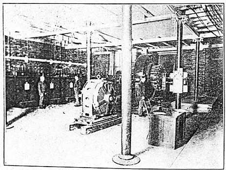
| Generating Switchboard in the Underground Station. |
Traveling the full length of the cavity and covering all of the machinery, are two 10-ton traveling cranes. These were used in installing the machinery and are available to handle the upper wheel housings when it is desirable to inspect the wheels and for such other purposes.
To really appreciate this plant one need only consider that it has a capacity of 10,000 electrical horsepower output, and including the main receiver and connections, water wheels, generators, traveling cranes, exciter, elevator gear, switchboard and all auxiliary apparatus is in a cavity 40 feet wide, 30 feet high and 200 feet long, every piece of apparatus being conveniently arranged for operation, accessible, and ample room being provided for all purposes; and to realize the ideal simplicity of the plant as an entirety one need only consider that the entire station of 10,000 horsepower output is regularly operated and cared for by two men on a shift, one an electrician on the switchboard and in charge of the station, standing a watch of eight hours, and the other an oiler serving a twelve-hour watch, whose principal work is one of inspection and keeping the entire station in good order. To better appreciate this, consider the crew required in a steam driven station of equal output with its gang of engineers, oilers, water tenders, firemen, coal passers and its dirt.
| |||
| Excavating the Tailrace Tunnel. |
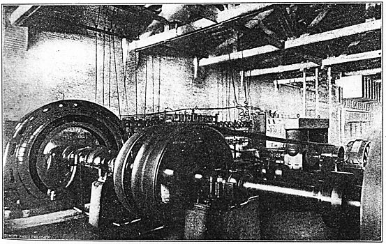
THE GENERATORS.
The generators are of the revolving-armature type and deliver a three-phase current at 1000 volts, 7200 alternations and each weighs about 100,000 pounds and stands 14 feet high. The normal full load current is 1000 amperes per conductor. The armature winding consists of 266 bars with one bar per slot, and is a closed circuit winding. The armatures are 96 inches in diameter and weigh approximately 24,000 pounds each. The speed is 300 revolutions per minute and the peripheral velocity is accordingly nearly a mile and half a minute. Massive collector rings of the ventilated type deliver current to the external circuits. Three brushes hear on each ring, and to insure equal division of current between them in case of unequal contact resistance, separate cable leads of considerable length connect brushes and the outside circuit in order that the fixed resistance with each brush may be large compared with the possible variable resistance. The field frame is split vertically and rests on the bed plate which supports the armature bearings. Poles are laminated and cast in the field frame. The field winding is of one-layer copper strap bent cold on edge and afterward insulated. At each end of a coil are brass brackets which rigidly hold it on the pole piece, exposing both inside and outside surfaces to air circulation to carry away heat. This form of construction produces a coil that is very easily insulated, furnishes a maximum surface for ventilation, and at any time may be easily repaired in case of accident. At no load these generators require a field current of 95 amperes at about 90 volts, and with full non-inductive load, 100 amperes to maintain the same electromotive force.
| |||
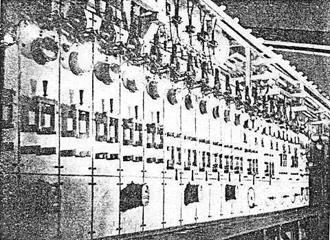
| High-Tension Fused Switches. Plugs for Multiple Plugboard, Etc., in the Primary Station. |
| |||
| Opening A 30,000-Volt Circuit-Breaker Carrying Line-Charging Current Only. |
Speed regulation in a water power plant depends greatly on the kinetic energy in the moving parts. In these armatures about 4,500,000 foot-pounds of energy is stored at 300 revolutions per minute, and from the construction of the water motors the moving water column also contributes to the stored energy, since it operates directly upon the revolving pints of the water motor, The water column in penstock and receiver weighs about 600 tons, and, with one water motor running, has only 67,000 foot-pounds of kinetic energy, or about 1 ½ per cent. of that in a generator armature. When all the water motors are in operation the water contains much more kinetic energy, but it is still of little importance compared with that stored in the revolving armatures. The stored energy in a single revolving armature is equal to the electrical output of that armature at full load in four seconds.
There are provided two separate 125-volt exciters each of 75 kilowatts and each being more than sufficient in capacity to supply field current to all four of the generators. These exciters are each separately driven by a 100-horsepower wheel, mounted in steel housings. No automatic speed regulators are used here, since the load is perfectly steady, but the regulation of the "needle" valve is effected by hand.
THE GENERATOR SWITCHBOARD.
The switchboard is of white marble, with mountings of brass and bronze. It is 35 feet 5 inches long and 7 feet 6 inches high, and has 18 panels - 4 for the generators, 2 for the exciters and 12 for the feeders. It has two sets of busbars so that different classes of load may be carried separately. Current is conducted by lead-covered cables laid in sewer pipe in the cement floor from the generators to aluminum husbars extending along the south wall to the switchboard. These bars are supported by brackets on glass insulators. They are of pure aluminium, 0.2X3 inches in section and in 30-foot lengths. Three bars carry 1000 amperes with a very moderate rise of temperature. The joints are lapped and bolted, and connection to the switchboard is made by cables with brass terminals which are bolted to the bars. The exciter panels carry ammeters, circuit breakers, ground detectors, voltmeter and plugs and rheostats. Each generator panel has circuit breakers on two of the three phases, synchronizing and pilot lamps, field ammeter, a main ammeter on each of the three circuits, indicating wattmeters of the Niagara type, a field rheostat, double-throw three-pole switches, and voltmeter and ground-detector plugs: The feeder panels have circuit breakers, ammeters and a double-pole double-throw switch, so that each feeder may be put on either the upper or lower busbars. The switchboard also carries three alternating-current voltmeters on swinging brackets, by means of which the voltage in any phase of any generator may be read, connection with the various panels being made through the voltmeters' bus-bars. The wattmeters are arranged by a simple combination of series and shunt transformers, so that their indication is the same as if they were on a two-phase circuit. This is of considerable value, as the indications of the meters remain equal with a balanced load even if the power factor on the three-phase circuit is less than unity.
| |||
| Step-Up Transformer House at Head of the Shaft. |
To prevent the generators from attaining too high a speed in case of a large amount of power suddenly going off of the system, a water-cooled rheostat is provided. This is in the form of an immersed wire resistance, being composed of spirals of No. 10 B. & S. gage iron wire connected in series of 48 per frame with six frames in multiple per phase, giving about two ohms resistance per phase, and three sets of frames being contained in a tank of running water, delta connection. Three panels are added to the switchboard to serve the rheostat, each panel being equipped with a circuit breaker and a double-pole double-throw switch, so that one or more of the phases may be thrown on the rheostat, or so that it may be used on either the upper or lower busbars.
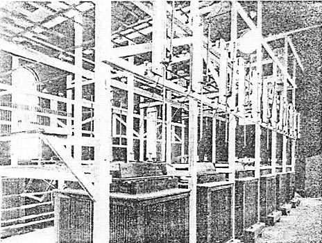
TRANSFORMERS.
From the feeder panels of the switchboard 24 aluminum cables are provided for conducting the 1000-volt current up the elevator shaft to the transformer house, which stands just east of, and contiguous to, the intake. These cables are bare and are carried on ordinary glass cable insulators supported on timber framework built in the shaft. The transformer house is a fireproof building of brick and iron with concrete floor and slate roof. It is 40 feet by 60 feet and 30 feet high.
There are 12 raising transformers and one extra one for use in case of accident. These are arranged in two rows longitudinally, with an aisle space on each side and a space between for the incoming 1000-volt circuits.
The raising transformers are of the standard Westinghouse self-cooling oil-insulated type, and have a capacity of 550 kilowatts each. Their cases are 55x72 inches and 66 inches high and each contains 500 gallons of oil made specially for transformer use. The experience of the Snoqualmie Falls Rower Company with various transformer oils in high-tension transmission service was such that eventually it wisely determined upon the use of only such oil that, upon exhaustive test, should prove itself to be entirely free from acid and all other matters injurious to insulation. The result has been that such a transformer oil is used exclusively in the Snoqualmie transmission system; and it is interesting to note that the total amount of this oil now in use is practically 20,000 gallons.
The primary winding of these raising transformers is for 1000 volts and the secondary winding is convertible for either 15,000 or 30,000 volts. Each complete transformer weighs, approximately, 10,850 pounds, of which 3600 pounds are in iron and copper. These transformers have a very low self-induction. With one of these windings short circuited, less than three per cent. of the normal electromotive force at 7200 alternations per minute will send full load current through the other coil. This is due to subdividing and closely sandwiching the primary and secondary coils, which are thin and flat.
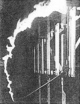
The high-tension coils have many layers with but few turns per layer, and each layer is wound in the same direction, so as to reduce the difference of potential between the successive layers. At the end of each layer the wire is carried across the face of the coil to the starting side. The low-tension coils are of bars or straps wound on edge and afterwards insulated. The coils are spread at the ends outside of the iron core to facilitate oil circulation which carries away heat, and also to increase the distance between the coils where it is difficult to apply solid insulation. Both the primary and secondary circuits of the raising transformers are connected in delta. To protect attendants and apparatus in case of accidental contact between high-tension and low-tension windings, spark gaps are connected between each low-tension winding and the earth. Each transformer is supplied with two high-tension fuse circuit breakers by which it may be disconnected either by hand or automatically in case of excessive current load. The fuse circuit breaker consists of two hinged wooden rods by which the fuse terminals are widely separated, breaking the arc when the fuse is ruptured by the current. The electric arc from this circuit breaker when it operates at 30,000 volts is six feet long. Although it is said that lightning occurs only once in about four or five years, each incoming line wire is protected by a Wurts lightning arrester of improved construction. On the front of a vertical slab, 24x65 inches, are mounted the spark-gap cylinders (in units of seven) in separate porcelain cases, while on the back of the same panel are six choke coils mounted on three marble wings which support the coils and insulate them while they are, brought in close inductive action with each other.
| |||
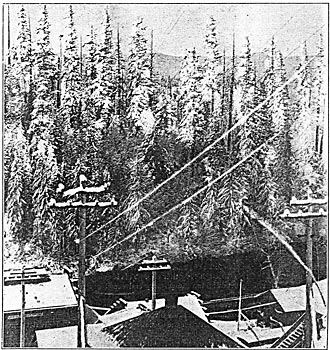
| 30,000 Volts on A "Cold" Line With This Snow, and No Trouble. |
An elaborate high-tension plug-board has also been constructed overhead in this transformer house, by the use of which any combination of transformers and circuits can be arranged. The lower (transverse) bars of this plug-board are connected to the raising transformers, and the upper (longitudinal) bars, which are about twenty inches above the lower bars, are connected to the outgoing wires, all connections being through fuse circuit breakers. The connections as desired are made by means of copper plug-rods that are manipulated with a long wooden insulating detachable handle.
|
POLE LINES.
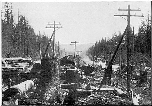
The district traversed by the transmission lines varies from mountainous to rolling and flat country. The right of way for the pole line is owned by the company, with the exception of several stretches where the county roads are occupied under a franchise. The right of way is patrolled daily by men on horseback, each patrolman having a distance of ten miles, and reporting by telephone to Seattle and the Falls from the telephone booths located every three miles. This patrol service has been organized for the purpose of detecting any weakness that may appear in the line and to protect it from any dangers that may threaten. The right of way is, in general, 50 feet wide. In many places, however, the company has a timber right for a distance of 300 feet on each side of the line, with the privilege of felling timber which might injure its operations. This right has been exercised at considerable expense, and trees eight or ten feet in diameter, 300 feet high and 300 feet from the line have been cut, assuming that if they fell they might reach the line and damage it. Now no falling tree can possibly reach the pole lines.
| |||
| Clearing the Right of Way. A Characteristic View of the Country Through Which the Pole Lines Pass. |
The transmission wires are of aluminum, and in this the Snoqualmie company divides with the Standard Electric Company of California the distinction of being the first to inaugurate the use of this metal in long-distance transmission practice. The conductivity is about 60 per cent. of that of copper, so that the aluminum wire, in order to have a capacity equal to copper, must have a cross-section about 66 per cent. greater, but with this increased size the weight is slightly less than 50 per cent. that of copper. Longer spans are, therefore, possible, thus making a saving in poles and insulators, and its cost is also less.
The tie wires are of soft No. 8 B. & S. gage aluminum wire, and no electrolysis can occur with these ties, as would be the case with iron or copper wire. The aluminum transmission wires stop at the city limits of Seattle and Tacoma, and copper is used beyond these points for distances of one and a half miles and three-quarters of a mile, respectively. The joints of the line conductors are spliced with a modification of the McIntyre sleeve, which consists of a flattened aluminum tube nine inches long and one-sixteenth of an inch thick, the diameter being sufficient to receive the two line wires. When the joint is made, it is given three complete twists by special clamping tools.
The poles are of cedar, nine inches in diameter at the top, stripped of the bark and either burned or tarred at the butt. The standard length is 36 feet, set six or eight feet in the ground, but the length ranges from 36 to 154 feet, according to the nature of the country. At the crossing of the channel in the harbor of Tacoma there are four poles about 154 feet long, 47 inches in diameter at the butt and 23 inches at the top, weighing 25,000 pounds each. The poles, which were erected with a piledriver, were set in line with a transit and their lengths conform to grades established by the engineers.
The cities of Seattle and Tacoma are reached by separate pole lines. These are parallel and 40 feet apart as far as Renton, 19 miles, where they diverge to their respective terminals: Seattle, 31 miles and Tacoma 44 miles.
| |||
| A Transposition, Showing Method of Line Construction. |
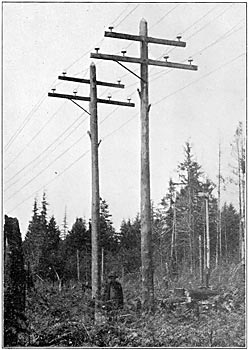
The lines are carried on triple-petticoat Imperial porcelain insulators of the Redlands type, 4 ½ inches high and 6 1/2 inches in diameter, weighing four pounds each. The pins are of locust, boiled in paraffin oil, and carry the insulators four inches clear above the cross-arms. Two circuits are run on each pole line, one on each side, with a triangular spacing of 30 inches between the wires. On the lower cross-arm are four wires, the inner ones 75 inches from the center of the pole and the other ones 25 inches from them; on another cross-arm, 25 1/2 inches above, are two wires, each 40 inches from the center of the pole. The cross-arms are 4 1/2x6 inches, eight and ten feet long. The whole line is substantially built, with poles braced whenever necessary, while double cross-arms are used on all curves and turns and crossings. The length of span on the Seattle line varies from 90 to 150 feet, but the average is 110 feet. On the Tacoma line, the average span is 150 feet. A sag of about 15 inches is allowed, this being considerably greater than is common practice with copper wires. The lines are divided into six equal sections on either side of the Renton sub-station by means of transpositions. The spans in which these transpositions are made are between poles set six feet apart, which effectually prevents accidental contact between wires. At each transposition the circuits are given one-third of a turn, always in the same direction.
A telephone line of No. 10 B. & S. gage aluminum wire is carried about five feet below the power circuits on ordinary glass insulators on brackets. It is transposed at every fifth pole. The patrolmen carry portable telephones, so that a call can be made by climbing any pole. Telephone booths, containing also line supplies and tools, are located at intervals of three miles.
SUB- STATIONS.
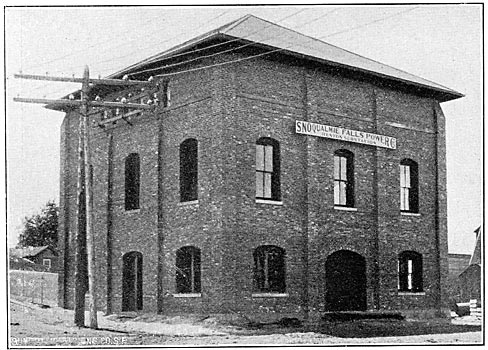
The first sub-station is at Issaquah (formerly called Gilman), ten miles from the falls. This is a coal mining settlement of about 1200 people. Here a small brick station has been erected from which to distribute current for lighting the town and furnishing power to the coal mines. It contains a Westinghouse oil-insulated air-cooled lowering transformer of so kilowatts capacity, and from 30,000 to 2000 volts with variable secondary, the current therefore being taken from one phase of one of the Tacoma circuits. There is a fused high-tension circuit breaker in each of the two wires to the transformer. The station serves also as a residence for the patrolman on this section.
| |||
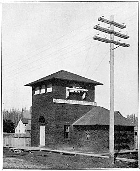
| The Sub-Station at Renton. |
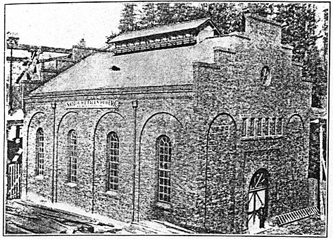
The next sub-station is at Renton, 19 miles, where a brick building 40x40 feet, and 22 feet high, has been erected for the high-tension apparatus and power apparatus, and this also forms the home of the man who has charge of the station and patrols the adjacent section. It contains a 50-kilowatt, 30,000-volt to 2000-volt lowering transformer as in the Issaquah sub-station. The high-tension wires enter the building through marble and glass bushings, and there is a high-tension plug-board, similar to that at the generating station, which admits of making any combination of the incoming and outgoing circuits. Each wire has a high-tension fuse switch. The town has a population of 2000, and is in a farming district. Extensive coal mines in the neighborhood are expected to be eventually operated by electricity furnished from this station.
| |||
| The Sub-Station at Gilman. |
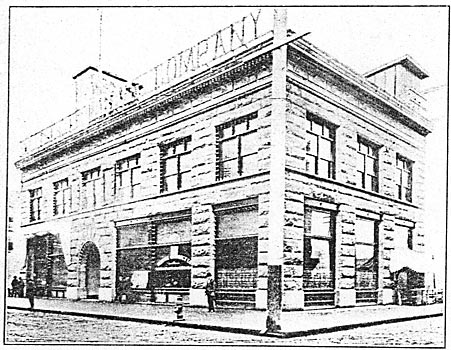
The terminal sub-station at Seattle is located in the business district. It is a substantial Tenino sandstone building two stories in height. The transformers and other apparatus have been installed in the basement, while the two floors above are occupied by the company's offices.
The 30,000-volt circuits are carried to the building on 70-foot poles, the wires entering a tower on the roof, about 40 feet above the ground, through glass tubes set in marble panels. Thence they are carried through a terra cotta shaft to the lightning arresters which are the same in number and similar in arrangement to those at the raising transformer house at the falls.
On the ground floor are high-tension fuse switches by which the incoming current may be controlled. All of the load may be placed on either transmission circuit, or it may be divided so that the steady load is on one circuit and the fluctuating load on the other, or both circuits may be connected in multiple. The switching apparatus is of extreme flexibility. There are also high-tension fuse switches for the lowering transformers located in the basement.
There are at present three step-down static transformers with primaries and secondaries in delta connection, for supplying 350-volt current to the 500-volt rotary transformers. The primary coils may be connected either for 12,500 volts or 25,000 volts. The secondary coils have intermediate terminals by which the electromotive force supplied to the rotaries may be adjusted when necessary. Otherwise the transformers are similar in construction and capacity to those of the generating station. There are also four pairs of two-phase to three-phase lowering transformers of 300 kilowatts capacity each, and two pairs of 500 kilowatts each, with 2000-volt secondaries for general lighting and power distribution, which makes the total station transformer capacity 3700 kilowatts. These transformers are equipped with potential regulators by means of which the secondary voltage may be changed to suit the conditions of variable loads.
White marble switchboards are furnished for controlling the three rotary transformers. Each of the alternating-current panels contains a three-pole single-throw washer switch, three ammeters, synchronizing lamps, field rheostat and a switch for the starting motor on the rotary. On each direct-current panel are a circuit breaker, ammeter, voltmeter, plug receptacles, and two single-pole washer switches. The feeder panels have circuit breakers, single-pole washer switches and Thomson recording wattmeters. Voltmeters are mounted at the end of the board on a swinging arm.
There are two rotary transformers of 500 kilowatts capacity delivering current at 550 volts, which are operated in multiple on both alternating end direct current sides. A third rotary of equal output has been ordered. These rotary transformers have 18 poles and run at a speed of 400, revolutions per minute. Collector rings and brushes are like those on the generators but of smaller capacity. To bring the rotaries in synchronism without excessive starting current, a small induction motor is mounted on the armature shaft. As this has 16 poles, it is enabled to bring the rotary armature slightly above synchronism.
| |||
| The Snoqualmie Building, Seattle. - Office and Sub-Station. |
For alternating-current lighting and power-motor work, a panel is provided for each set of three-phase, two-phase transformers, containing two 2000-volt automatic circuit breakers, two ammeters, two Niagara-type indicating wattmeters, two double-pole throw switches and pilot lamps. The feeder panels are the same, except that polyphase integrating wattmeters of the Westinghouse type are used instead of the indicating wattmeters. In making changes on these hoards the circuits are first opened by the circuit breakers as the switches are not designed to break current.
The Tacoma circuits pass through Auburn and Kent, each having a population of about 1000, and being in a farming and dairy district. A small sub-station has already been established at Auburn, 31 miles from the falls, and another is to be established at Kent, 25 miles. The former place is on the Northern Pacific Railway, Where its lines from Seattle and Tacoma meet the main overland line. The Auburn sub-station contains a 50-kilowatt lowering transformer the used as used at Issaquah.
| |||
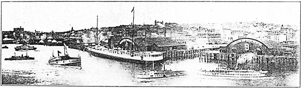
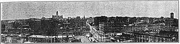
| The City of Seattle. |
The terminal sub-station at Tacoma is a red brick structure, occupied jointly with the Tacoma Railway and Power Company. The line circuits are equipped with high-tension fuse switches as at Seattle, by means of which the transformers may be connected to either circuit or in multiple.
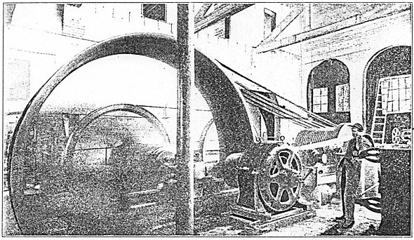
The Tacoma station is equipped with three 500-kilowatt transformers and two 500-kilowatt transformers, similar in type and style to those at Seattle, making 2100 kilowatts total capacity at Tacoma. These transformers are also equipped with the potential regulators on the secondaries of the transformers as at Seattle. To take the place of steam engines and in order to utilize Snoqualmie electric power, the Tacoma Railway and Power Company has installed a 1000-kilowatt, two-phase, 2200-volt General Electric synchronous motor of the revolving field type. This is used to drive a long jack-shaft having a diameter of nine inches and front which are belted a number of railway generators and series-arc machines.
| |||
| A Corner in the Seattle Sub-Station. |
The Tacoma company also has a 100-horsepower, 2200-volt General Electric induction motor which drives the rope drum of the cable railway system of Tacoma. In addition there are two 750-horsepower General Electric motor-generator sets, each consisting of a 2200-volt induction motor and a railway generator mounted ou the same base-plate, the armatures on the same shaft and the field frames close together. A very complete switchboard is provided for these motors as well as for the railway feeders and for the 2000-volt distribution about the city.
By the use of the plug switching boards at the generating station and at the Renton sub-station, and of the paralleling switches at the Seattle and Tacoma sub-stations, it is possible to form a single continuous three-phase circuit from the generating station at the falls to Seattle, back to the falls, to Tacoma and back to the fallsa total distance of 153 miles. Such a line would he constituted as follows:
 |
For several hours during the daytime of November 18th last, the various distributing services of the company were cut off and the transmission circuits were connected up as one in the manlier above indicated, and the record feat of driving a motor 153 miles distant from the generator was performed.
Before making the transmission tests the circuit to Seattle and back, 62 miles, was tested, and the ohmic resistance was found to be 86 ohms; likewise the Tacoma circuit of 91 miles was found to be 152 ohms, the complete circuit of 153 miles giving 241 ohms. Current front the exciter was used for making this test, the resistance to ground being 700,000 ohms.
| |||
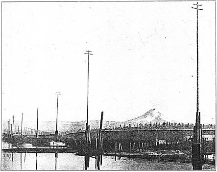
| 154-Foot Poles on the Line Entering Tacoma - Mount Rainier in the Distance. |
The long-distance transmission tests were conducted for experimental purposes only, and to show that electrical transmission of power can be made commercially practical at much greater distances than has heretofore been contemplated. One of the Westinghouse 1500-kilowatt, three-phase generators furnished the current, and a similar machine was used as a synchronous motor at the end of the circuit. A bank of the raising transformers was used as lowering transformers and one of the feeder circuits was used to convey the current down into the generator chamber to the switchboard. Only the regular switchboard instruments were used for the readings. Where kilowatts are given they are the sum of the wattmeters and are not kilo-volt-amperes.
| |||
| The City of Tacoma. |
With the 153-mile circuit open at the incoming end, the tests were made for charging them at different voltages, the alternations (7200) being kept constant. It was found that as the voltage increased, the charging current rapidly increased; at 22,500 line voltage it required 62 kilowatts to charge the line, at 30,000 volts it required 112 kilowatts, and at 35,000 volts it required 180 kilowatts. With the lowering transformers at the falls cut in and their secondaries open, it was found that the current required to charge the line increased; at 22,500 volts it required 76 kilowatts, and at 30,000 volts it required 123 kilowatts. The voltage at the incoming end of the circuit, with charging current only on the line, was greater than at the outgoing; 22,500 volts out, gave 24,600 in, and 30,000 volts out gave 32,100 in. Tests were also made to determine the different amount of charging current required at different frequencies, the voltage being kept constant at 30,000, and it was found that at 6000 alternations 100 kilowatts were required to charge the line; at 6600 alternations, 105 kilowatts; and at 7800 alternations, 115 kilowatts.
The line was then tested for loss of power in transmitting a non-inductive load, consisting of the water rheostat at the falls at the end of the 153-mile circuit. It was found that the line voltage out was 30,000, incoming 22,500, drop 25 per cent. The amperes per phase at 1000 volts out was 624, incoming 354, loss 11.2 per cent. The total kilowatt outgoing was 1100, incoming (that is delivered into the water rheostat tanks) 723, loss 34.2 per cent.
| |||
| A 1000-Horsepower Synchronous Motor Driving the Tacoma Railway Company's Electric Power House. |
A test was also made for charging current with the sub-station transformers at Seattle and Tacoma, and the lowering transformers at the falls in circuit, but with secondaries all open, and it was found that with the 30,000 volts out, there was 31,500 volts in, and that it required 193 kilowatts to charge the line. A test was then made of operating a second generator as a synchronous motor at the end of the circuit and the machines were synchronized without any trouble whatever; but they soon began pumping so that it was found advisable to separate the machines. During this test the outgoing line voltage had varied front 26,700 to 27,600 and the incoming from 24,000 to 26,700, giving approximately a drop of six per cent., the amperes per phase at 1000 volts out being approximately 900; incoming, approximately, 650; loss, approximately, 27.7 per cent. Total kilowatts out, 432; incoming, 374; loss, approximately, 13 1/2 per cent. The figures on this last test are approximate only, as all of the instrument needles oscillated very much, many of the ammeters fluctuating over the entire range of the scale. The foregoing losses would be greater or less according as the loads carried might be increased or diminished.
The experiment was then tried of operating the water rheostat and the synchronous motor in multiple at the end of the 153-mile circuit and the performance of the motor was very much improved. The water was then shut off from the water wheel and the driven motor at once reverted to a generator driven by its own inertia.
MARKETS FOR SNOQUALMIE POWER.
The Snoqualmie Falls Power Company furnishes power for both lighting, railway and general power purposes, and it is expected that many of the manufacturing plants of Seattle and Tacoma will soon be operated by the power from Snoqualmie Falls. The power in Issaquah, Renton and Auburn is used for lighting purposes only, for both incandescent aid arc lights. In Seattle, all the stationary motors are being operated, and the entire municipal street lighting system; also the Centennial flour mill, 2000 barrels daily capacity, the Capital flour mill, 300 barrels daily capacity, and about half the street railways. All the street railways will soon be operated from this service. In Tacoma, the municipality owns the lighting system and power is purchased for the purpose of running it. The Snoqualmie power is furnishing nearly all the lighting circuits in Tacoma at present, and the others are to be added as soon as the transformers have been changed to adapt their distribution to the frequency of this plant. All the electric roads are under contract and will take the current as soon as the induction motors which are to drive a line shaft have, been installed. An induction motor is also employed at Tacoma in a grain elevator for loading ships.
The manufacturing plants in Seattle and Tacoma include three flour mills, a smelter, ear shops, several iron works, elevators, machine shops, etc. The operation of the municipal water works pumping station for Tacoma is also contemplated. Negotiations are also in progress for the establishment of electrolytic and chemical works. Almost the entire output of power was contracted for before the Snoqualmie Falls power plant was in operation. The first customer was the Centennial Flour Mill Company, of Seattle, which contracted for power nearly a year before the completion of the plant. All the machinery for operating the null, including that for grinding, cleaning, ventilating, receiving and delivering the grain and flour by elevators, etc., is operated by two Westinghouse motors of 200-horsepower each, which have entirely supplanted the steam power equipment. A third 200-horsepower motor has been ordered, so that the capacity of the mill may be increased.
The city of Seattle has a population of 80,600; Tacoma, 38,500, and Everett, 10,000. These three cities and the neighboring towns are rapidly growing and increasing in industrial importance, and many small industries and factories, large in the aggregate, are being established. The Snoqualmie Falls Power Company does not engage in the distribution of power to small customers, but sells power in large blocks for this purpose to the Seattle Cataract Company and the Seattle Electric Company, in Seattle, and the Tacoma Cataract Company and the Tacoma Railway and Power Company, in Tacoma. It reserves for itself the duty of supplying large plants of every description which can be reached by any of its lines or extensions. A transmission line to Everett is proposed, 35 miles from the falls, where a. paper-null, smelter and other industries in operation would take 2000 horsepower. The company's policy is to build up a business of large volume at moderate prices, rather than small volume at high prices.
| |||
| A 100-Horsepower Induction Motor Driving the Tacoma Cable Railway System. |
The waterfall and the land on either side were purchased in the autumn of 1897 by Wm. T. Baker, of Chicago, who organized the Snoqualmie Falls Power Company early in 1898. Work was commenced as soon as the organization of the company had been perfected. The construction plant included two 125-horsepower boilers, an air compressor delivering air at 100 pounds pressure into a receiver 4 1/2 feet diameter and 12 feet high, 10 rock drills working under 60 pounds pressure, and a sinking pump with a five-inch suction and four-inch discharge to keep the shaft excavation dry. Owing to the solid character of the rock, however, very little water entered the excavation. It was surrounded by a cofferdam 15 feet high to prevent flooding in case of high water in the river. Over the shaft was a hoisting trestle 50 feet high, for the cages, which were operated by a 75-horsepower double friction drum engine, which could raise a load of 6500 pounds at a speed of 450 feet per minute. The rock dumped at the trestle was carried by a gravity tramway to a crusher with a capacity of 70 cubic yards. This was driven by a 15-horsepower engine, and crushed stone was piled up for future use in the concrete work. All the concrete was mixed by hand.
To supply air to the drills in the tunnel, a pipe line was extended 400 feet to the edge of the cliff, and a section of pipe lowered to the bottom, a depth of nearly 300, feet. Two men suspended by ropes, and working in the whirling spray and wind of the chasm, put the pipe lengths together, building it up from the bottom and constructing the necessary timbering to support it against the rough face of the cliff. At first, all tools and material had to be carried up and down a winding stairway, but a standing cable was soon put in place, on which ran a box for tools, operated by means of a windlass.
For handling heavy material, a trestle was built over the sidetrack and extending to the shaft; upon this was a traversing hoist, by which the material was raised from the cars and carried to the works. The first drill was set in operation on April 17, 1898, and the work was then prosecuted by day and night until completion. The first water wheel and generator in actual operation delivered current into Seattle July 31, 1899, and into Tacoma, November 1, 1899. A number of features yet remained to be completed, so that the plant has only recently been fully installed. The finished enterprise will represent an investment of about $1,000,000.
A substantial brick building, 34x50 feet, with slate roof, has been erected near the transformer house for use as a repair shop, with separate rooms for the machine shop, carpenter shop and blacksmith shop. The machine shop contains a 12-foot, 20-inch lathe, a 28-inch drill press and a 24-inch shaper. This building also contains the company's headworks office and a storeroom. About 27 acres of ground covering the works, the brink of the falls and both banks of the river have been laid out as a park, with lawns, walks and flower beds, the grounds being illuminated by arc lamps. Comfortable cottages and a dormitory, with all modern conveniences, have been erected by the company, and there is also a cottage for the executive officers and for visitors.
PERSONAL.
Of this company, Charles H. Baker is president and general manager, and the other officers are as follows: vice-president, A. H. Andrews; secretary and treasurer, George G. Lyon; manager at Tacoma, James C. Drake. The company has its main offices at Seattle, Wash., and a branch office at Tacoma, Wash. Thomas T. Johnston, consulting engineer of the Chicago Drainage Canal, was consulting engineer during the construction of the works, and James J. Reynolds was the superintendent of construction.
The electrical engineer was E. M. Tingley and Robert McF. Doble was mechanical engineer and superintendent during the installation of the water wheels and final completion of the plant. The construction work was done by the company and not by contract.
Of these, the interest of the public centers in Wm. T. Baker, who is the organizer and sole owner of the Snoqualmie Falls Power Company, and in his son, Charles H. Baker, under whose general management the work has been carried through to its present successful outcome. To them more than passing reference should be made. William T. Baker was born in Winfield, Herkemer county, New York, September 11, 1842. His early education was confined to the country school and ceased at
 |
