[Trade Journal]
Publication: The Central Station
New York, NY, United States
vol. 8, no. 8, p. 176-178, col. 1-2
The 110,000 Volt Transmission Line of the Grand Rapids Muskegon Power Company.
Considerable interest has been aroused by the 110,000 volt transmission line of the Grand Rapids Power Company which, now that it has been operating satisfactorily for six months, has proved the entire practicability of this voltage for long distance electric transmission of power. The line is insulated entirely by General Electric insulators of the disk type, and the following notes may be of interest.
| |||
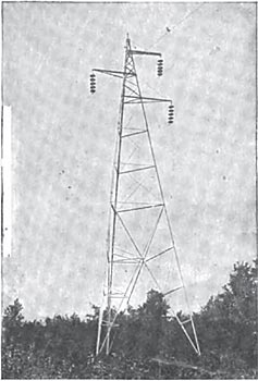
| Fig. 1. 53-Foot Transmission Tower. |
| |||
| Fig. 2. Transmission Tower. |
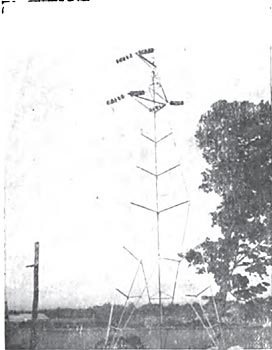
This transmission line runs between Grand Rapids and the Croton Dam, Michigan, and is fifty miles in length. The line is carried on triangular steel towers which are approximately 53 feet in height over all and 43 feet 8 inches from the ground to the lowest cross arm, and which were designed to give a 40 foot clearance between the line wire and ground. The towers weigh approximately 1,700 pounds each and provide a minimum spacing between the insulator hangers of 8 feet; they are placed on large concrete anchors buried in the ground, and are spaced 528 feet apart on tangents (Fig. 1 and 2). The anchors consist of 3-inch angle steel, 7 feet 10 inches long, encased in concrete. The anchors each extend about ten inches below the bottom of the concrete in which they are encased, thus securing a ground for the transmission line.
| |||
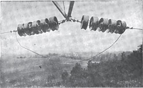
| Fig. 3. Disk Pattern, Strain Type, Insulators. |
In view of the many troubles experienced by the large majority of companies when first starting a high-tension transmission line using pin insulators, a report made on the operation of this line is of special interest. This report states that "this line has been in operation since July 18th last and we have experienced no trouble whatever. Nothing of an unusual nature has occurred and we consider its operation as very satisfactory and successful."
| |||
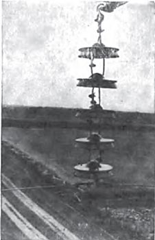
| Fig. 4. Disk Pattern, Strain Type, Insulators. |
The majority of the right of way is located along the highways, and only a tower right was taken. Where the line passes through forests or makes short cuts across country, a strip of land was purchased, varying in width from 33 to 66 feet, according to circumstances. This land is usually fenced off. No protection whatever is used where the lines cross highways or traffic routes.
| |||
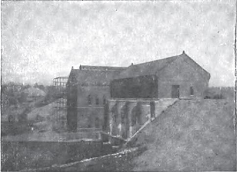
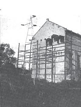
| Fig. 5. Croton Dam Power Station. |
| |||
| Fig. 6. Croton Dam Power Station. |
The insulators are of the standard General Electric disk pattern, the suspension type being used for a straight support and the strain type for pull-off curves. Five of these 10-inch disks are used in series, the arrangement being very clearly shown in Figs. 3 and 4. Each disk is rated at 25,000 volts.
The line transmits 10,000 k.w., the conductors consisting of No. 2 stranded hard drawn copper wire with hemp center. The lines are spaced 8 feet apart and are entirely without transposition throughout the whole length. No guard wire is used.
The lines are brought into the stations through porcelain insulators and are connected directly to the high-tension transformers, which are delta connected on both sides. There are no switches of any kind in the lines, the control being by means of generator field switches.
The pressure was first applied to the transmission line on July 18, 1908, and it was noticed that the line was a little noisy at the working pressure of 110,000 volts, while at night the atmospheric discharge was distinctly visible. Wattmeter rating on the empty line, after deducting the core losses of the step-up transformers, seemed to indicate a constant loss on the 50 miles of line of from 20 to 25 k.w.
| |||
| Fig. 7. Static Discharge From the Line. |
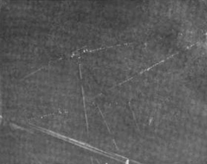
Other interesting features of the line are shown in Figs. 5 to 7 inclusive.
