[Trade Journal]
Publication: California State Mining Bureau, Twelfth Report of the State Mineralogist
Sacramento, CA, United States
p. 413-432, col. 1
ELECTRIC POWER TRANSMISSION PLANTS AND THE USE OF ELECTRICITY IN MINING OPERATIONS.
By THOMAS HAIGHT LEGGETT, of Bodie, Mono County, California.
Some one has aptly spoken of California as the Switzerland of America. Certainly the rugged scenery of its snow-capped Sierra, and its numerous lakes and mountain streams, justify, in part, the simile. In Switzerland they have been quick to realize the advantages to be derived from the utilization of their water powers for the generation of electric power, and its transmission to distant points; here, in California, we are but beginning to grasp the situation.
In electricity the miner has undoubtedly gained a most efficient and valuable ally. Through its aid the latent power of the many streams now running idly down the mountain slopes can be made available, and brought across long stretches of country by means of a simple line of wire, to operate the machinery of mine and mill.
In sections where no water powers are available, and fuel is scarce and dear, electricity may be generated at the center of fuel supply, and the power transmitted from this central station to operate a number of mills and hoisting works in the distant mining camp. One of the great advantages of electric power is its adaptability to ready subdivision into small units without material loss of power, by reason of the high efficiency now developed by the best types of dynamos. Hence, separate motors may be used in the mill for running crushers, stamps, concentrators, pans, etc., or in the mine for hoisting-engines, pumps, and air compressors, effecting a very appreciable saving when any of these machines are idle. To accomplish this requires the use of the direct current, but this can be readily obtained from the alternating where such is used for the transmission, by employing rotary transformers, or "motor generators," of high efficiency.
In a letter to the writer, accompanying photographs illustrating the Telluride, Colo., transmission plant, hereinafter described, Mr. Chas. F. Scott gives the following excellent resume of the present status of electricity in the field of mining:
"In the introduction of electrical apparatus to the operations of the mining industries of the West, the field of electrical power transmission is extending upon lines which have already been well established in other industries. The electric motor is becoming an important factor in almost every industry in which power is utilized. One of the most notable instances is in electric traction. The electric street railway motor has not only almost entirely replaced animal power, but it has wonderfully increased the speed, comfort, and economy of street railway operation, and has also extended it to distances and classes of service which were previously impracticable. The early railway motor had many and peculiar difficulties to overcome, but the problems incident to it have been rapidly surmounted.
"Results similar to those which have been attained in street railway working are to be anticipated in the application of the electric motor to the mining industry. Not only will the work which is now performed be done in .many cases with increased ease and economy, but the introduction of the motor will lead to new methods of operation. Mining possesses many difficult and peculiar requirements for the application of power. The motor, on the other hand, possesses characteristics which render it capable of being adapted to a very great variety of conditions.
"The work which has already been accomplished in the new plants which have been installed, promises much for the future. The first work has been under difficulties which are incident to every new undertaking. The principal difficulties which have manifested themselves are, however, not fundamental ones; they are principally due to mechanical difficulties which are more or less readily recognized, and usually indicate a ready method of solution. A second trouble, which has promised at times to be very serious, is the effects resulting from the atmospheric conditions in the mining country. Lightning in many places has been extremely severe, and methods of protection were required which were impossible to devise before the conditions had been learned from experience. The necessity for protection has been followed by the means of protection, and electrical installations need no longer be in peril from lightning, if properly protected.
"The experience and progress which have come from other applications of electricity can be taken advantage of in application to mining work. The constant improvements and advances which are being made in the manufacture of electrical apparatus make it possible to secure at the present time apparatus which is better adapted for its work than could have been secured a few years ago.
"There is often an apprehension, on the part of those who are not familiar with electrical apparatus, that it is a fundamental failure if it does not at once begin and continue in satisfactory operation. Those, however, who are acquainted with electrical machinery, and who understand the nature of the difficulties which develop, may readily see that the fundamental elements in electrical power transmission and distribution are not involved in these difficulties, but that they arise from incidental features which can be readily corrected. The work which has already been accomplished shows the possibilities which are open in the field of electrical mining, and promises much for the future."
The transmission of 100 horse-power a distance of 109 miles, from Frankfort to Lauffen, Germany, in 1891, showed conclusively that from an engineering standpoint, at least, the transmission of power over long distances by electricity was perfectly practicable; though in this particular instance it was not a commercial success, nor was it intended to be, since the power was used for exhibition purposes only. Since then, however, plants have been installed both in Europe and in the United States, and are to-day successfully transmitting electricity for lighting and power purposes over distances ranging from 1 to 30 miles.
It will be proper to outline here the various methods of transmitting power over long distances by electricity, but for full information on this subject recourse must be had to the technical writers in the electrical journals and society transactions.*
*See W. F. C. Hasson's paper on "Electric Transmission of Power Long Distances," Transactions of the Technical Society of the Pacific Coast, Vol. X, No. 4; "Long Distance Transmission for Lighting and Power." by Chas. V. Scott, E.E., Vol. IX of Transactions of American Institute of Electrical Engineers; also pamphlet on Lone Distance Transmission by L. B. Stillwell, E.E., issued by Westinghouse Electrical and Manufacturing Co., Pittsburg, Pa.
Power may be transmitted by means of electricity by
1st. The direct or continuous current.
2d. The alternating current:
(a)Single phase, 2-wire synchronous system.
(b)Two-phase, 4-wire system. Either synchronous or independent speeds of generator and motor, as desired.
(c) Polyphase system; usually 3-phase with 3 wires. Either synchronous or independent speeds of generator and motor, as desired.
The direct or continuous current has the advantage that the motors are self-starting, and at practically full torque, or turning effect. The motor speed is quite independent of that of the generator, though this is not necessarily an advantage, inasmuch as, in synchronous systems, the governing of the generator speed regulates that of the motor as well, and therefore attention to the speed of but one machine is all that is required.
Direct-current dynamos labor under the disadvantage of working under comparatively low potentials, since they require a commutator to change the alternating current they generate into a continuous one, i. e., a current flowing constantly in one direction; and thus far it has been found impracticable to insulate this commutator for very high tensions. While it is asserted that* "direct-current machines of 5,000 -volts are in regular and successful use for arc-lighting," it must be borne in mind that the requirements for furnishing light a limited number of hours each day are very different from the demands made upon electrical machines by a stamp mill or hoisting works, which require unintermittent operation, oftentimes including Sundays.
* The "Electric Transmission of Power," Engineering Magazine, June 1894, p. 393.
Hence, such a high-potential, direct-current machine, if in good running order to-day, would hardly be serviceable for long-distance transmission, and indeed the staunchest advocates of the direct current in this country have never installed such a machine for this purpose.
On the contrary, in several cases where electrical companies known to favor the direct-current system have had contracts for the installation of long-distance transmission plants, they have not attempted such, but have instead used an alternating-current system in every case where the distance exceeded three miles.
It is safe, therefore, to conclude that until these difficulties of commutator insulation are overcome,* this distance is the practical limit for direct-current transmission, unless a series arrangement of generators and motors be resorted to.
* Mr. E. H. Booth, in an article entitled "Electricity as applied to Mining Operations," published in "Industry" for June 1892, says: "It is, however, a matter of difficulty to make commutators for potentials over 2,000 volts for direct-current generators, on account of the great number of segments required, and the difficulty of their proper insulation. While this voltage will De efficient and economical, both as regards cost of installation and of operation in many cases, conditions will also be met with requiring much higher voltages, which are at present commercially practicable only through the use of alternating currents."
A low potential necessarily limits the distance of transmission, since the size of wire is directly proportional to the number of amperes of current to be carried; and since amperes times volts equals watts, of which 746 are equivalent to 1 horse-power, it follows that to transmit 100 horse-power, or 74,600 watts, a given distance at a pressure of 500 volts (the ordinary voltage of a direct-current dynamo), would require a current of 149.2 amperes, or a wire six times as large (sectional area six times as great) as that needed to deliver the same amount of power over the same distance at an electrical tension of 3,000 volts (25 amperes X 3,000 volts = 75,000 watts = 100 horse-power).
The series arrangement of generators and motors alluded to has been introduced abroad, notably in Switzerland, and brought there to a higher state of perfection than in this country. This application of the direct current for long-distance transmission requires a number of generators and an equal number of motors, making a complicated apparatus of excessive first cost, especially so since extra dynamos and motors must be provided; otherwise an accident to one machine disables the entire plant.
At Genoa, Italy, there is such a transmission at present in operation. The power transmitted is 300 horse-power over a distance of 18 miles. At the power stations, of which there are three, one below the other, there are four groups of dynamos, each group of two dynamos being driven by turbines (Piccard system) of 140 horse-power, working under heads varying from 225 to 495 meters.
These dynamos are connected in series, one group being held in reserve in case of accident to any of the others, and produce each a current of 47 amperes at 1,000 volts electrical tension, the resulting E. M. F. sometimes reaching 6,000 volts during the hours of maximum load. The motors are also connected in series, no one machine, it will be noted, carrying a potential exceeding 1,000 volts at any time. The power is utilized in operating a factory at the terminus of the line.
The lack of flexibility of the system and its inadaptability to a wide and varied range of work have often been spoken of by technical writers, and these disadvantages have prevented its successful competition with alternating-current systems for transmissionsuch as that from Niagara Palls to Buffalo, where the power is to be utilized for a great variety of work.
It has been cited as an advantage of the direct-current system that it is not liable to trouble from the static capacity and self-induction of the line occurring with the alternating-current. Self-induction will reduce the potential at the motor end of the line, while static capacity will act in the opposite direction and increase the E. M. F., thus tending to counteract the effect of self-induction.
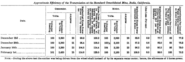
The discussion of these technicalities can safely be left to the electricians, but the writer can state from experience with a transmission by the alternating-current synchronous system of 120 horse-power over a distance of 12 1/2 miles that no trouble whatever has arisen from these causes. (See table showing the line-loss and the efficiency of this transmission.)
The three types of alternating-current machines, viz., the single-phase synchronous, the double-phase, and the three-phase generators, may, for purposes of comparison, be likened, respectively, to the single-cylinder steam engine, the double or two-cylinder engine with crank arms at 90°, and the three-cylinder engine with as many crank arms set at an angle of 120° each with the other; the electrical impulses bear just these relations with each other in the armature of the dynamo.
The single-phase generators and motors are necessarily synchronous, and the latter are not self-starting, but must be brought up to the generator speed before the line current can be led into its armature; while the polyphase machines are-self-starting under light load, but not under full load.
It is evident that for hoisting and similar work, where full load is thrown on the machine at once, alternating-current motors do not possess the advantages of direct-current machines, which start readily under such conditions, and for short periods can be greatly overloaded without damage.
If, therefore, it be desired to use electric power in all departments of a mining plant, the electricity being generated at a considerable distance from the works, cheapness of first cost and of copper conductors can be obtained by using a high-potential alternating system, with raising and lowering transformers if necessary; while by using rotary transformers, or motor generators, as they are sometimes termed, at the delivery end of the line, direct current can be obtained for all work requiring self-starting motors. These machines used for transforming alternating current into direct current at various potentials have a common field, and two windings upon the armature revolving within it, one of which receives the alternating current and acts as a motor, while the other generates the required direct current.*
* Induction motors (three-phase) are now being built by the General Electric Company, and quarter-phase machines by the Westinghouse Electric and Manufacturing Company, which it is claimed are fully equal in every respect to direct-current machines. This is a development only to be expected in view of the fact that the best electricians in the country have been devoting their best energies to the attainment of this most desired result;" and it will greatly simplify any quarter-phase or three-phase transmission plant where the power is to be used for the various classes of work required in mining.
For long-distance transmission the alternating current possesses the great advantage of being convertible from a low to a high potential, or vice versa, by means of a simple transformer, without moving parts, thereby effecting a great saving in copper, since, as already shown, the greater the E. M. F. the less number of amperes of current required to transmit a given power, and hence the smaller wire demanded. Singlephase, alternating-current motors, while not self-starting, may be heavily overloaded without pulling them out of synchronism and causing them to stop; and should the latter occur, no damage will result under ordinary conditions, since the self-induction of the armature will hold back the current for several minutes. They may be also heavily overloaded immediately after synchronizing. The 120 horse-power motor in the mill of the Standard Consolidated Mining Company at Bodie, Cal., has started all twenty stamps while resting upon the cams, though this, of course, is not the ordinary way of taking up the load. It shows that the motors will take an abnormally heavy load at the outset without damage beyond a little extra sparking at the commutator.
The two-phase four-wire system is equally adapted for both lighting and power, and it is not necessarily synchronous, though the advantage of speed regulation previously referred to makes it advisable to so operate the generator and motor wherever possible. It will furnish power through motors of either the rotating-field type (i. e., rotating magnetism) or the polyphase; and by means of commutating devices it can be made to supply direct current for all power and lighting work if so desired, and at a very high efficiency of transformation.
It is therefore particularly well adapted to. mining requirements, which, as stated, demand motors starting immediately and with full torque for certain classes of work.
"There are two especially prominent types of these machines. The first of these, the double machine, has two fields and two armatures, the latter mounted on the same shaft. Each armature delivers alternating current to a two-wire circuit, and these circuits taken together constitute the four-wire circuit of the generator; or they may be so connected as to constitute a three-wire circuit.
"Machines of the second type have single armatures with two windings, or with a single winding so connected to the ring collectors as to deliver two currents differing in their time relation or phase."*
*From "Transmission of Power," a pamphlet issued by Westinghouse E. & M. Co., and prepared by L. B. Stillwell, E.E.
Twelve machines of the first type and of 1,000 horse-power capacity were used by the Westinghouse Electric and Manufacturing Company as single-phase generators for lighting purposes at the World's Fair. Some of these were used for power to run exhibit motors, and in these cases were connected as quarter-phase (two-phase) machines.
There is a decided advantage in this system over the three-phase in the distribution of load on the two circuits of which it is composed, as the machine can be designed to regulate each current independently, i. e., maintain a constant E. M. F. with varying loads on the circuit, which cannot be done with the three-phase system. This advantage largely offsets the saving in copper of the latter system, which saving can be put roughly at about 25 per cent over that of either the single two-wire or two-phase four-wire systems. These latter stand on about an equal footing as regards the amount of copper required for transmitting power over a given distance at a stated potential.
"In a paper read before Section ' G' of the British Association, on September 18, 1893, Mr. Gilbert Kapp makes the following statement: ' If we put all the systems on the same footing as regards efficiency and safety of insulation, we find the following, viz.: For the transmission of a certain power over a given distance * * * the single-phase alternating and the two-phase four-wire system will require 200 tons, the two-phase three-wire system will require 290 tons, and the threephase three-wire system only 150 tons. As far as the line is concerned there is thus a distinct advantage in the employment of the three-phase system.' "
* ''The Electrical Engineer" (N. Y.), January 17, 1894, p. 42.
For the amounts and cost of copper required for transmitting power over varying distances and under different potentials, the reader is referred to the papers by Messrs. Hasson and Stillwell, already cited.
From the foregoing it would appear that for the ordinary work of stamp mills, where single large units of power are chiefly needed, the single-phase synchronous motors are well adapted to meet all requirements where the power is transmitted from a distance too great for the use of the direct current; while for a more extended and varied use of such power the polyphase systems are more economical and comprehensive, more especially the two-phase four-wire method.*
* For a full comparison of the relative advantages of the two-phase and the threephase circuits, see " Polyphase Transmission," by Chas. F. Scott, in the " Electrical Engineer " (N. Y.), March 21, 1894. In this article Mr. Scott proposes a combination of the two-phase and three-phase systems, generating under the first system, and by means of special transformers (while "also raising the potential if so desired) changing to the three-phase for the transmitting line and again converting to the two-phase current at the delivery end of the transmission, thereby uniting the advantages of saving in copper, of the one system, with those of greater simplicity, less cost of apparatus, and better regulation of the other method (the two-phase).
In the paper by Mr. E. H. Booth, already referred to, he speaks of the use of separate motors for each stamp battery, and for groups of four pans and two settlers each, thus doing away with heavy and expensive line-shafting, belt alley-way, etc.
Such an extreme subdivision of the power, however, would result in a heavy loss of efficiency, and is further highly impracticable at present on account of the high speeds at which electric machines operate, necessitating counter shafting to reduce the revolutions to the slow speed of pan and cam shafts. It is better, therefore, for milling work, to use a single large motor to operate the stamps, pans, etc., with perhaps one or two small ones for rock-crushers and concentrators in cases where the cost of the power or the production of higher-grade concentrates makes this an object.
The following description of the power-transmission plant of the Standard Consolidated Mining Company, at Bodie, Cal., is taken from the writer's paper read before the American Institute of Mining Engineers at the Virginia Beach meeting, February, 1894:
THE ELECTRIC POWER TRANSMISSION PLANT OF THE STANDARD CONSOLIDATED MINING COMPANY.
At Bodie, Mono County, Cal., the ruling price for wood has been, for years past, $10 per cord, so that the monthly fuel bills of a 20-stamp mill, crushing and amalgamating 50 tons of ore per day, would often amount to $2,000. To reduce this excessive cost of motive power was the problem in hand, and the use of electricity generated by water power has solved it. No sufficient water power could be found nearer than 12 1/2 miles, the distance from Bodie in a straight line over the hills to the east flank of the Sierra Nevada. This distance is just at that intermediate point where the cost of transformers about equals the difference in cost between a No. 1 and a No. 6 copper wire (it is not advisable to use any lighter wire than No. 6, on account of its liability to rupture during storms). Hence it was deemed better not to use converters, since they would only complicate the apparatus, without effecting a saving in cost.
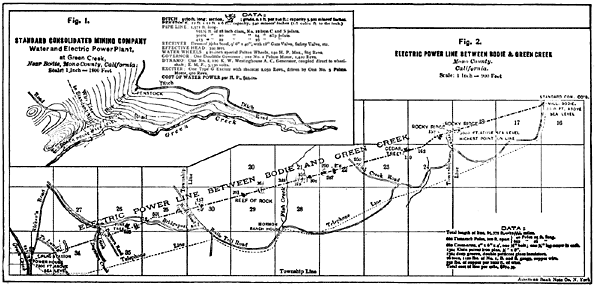 |
| Fig. 1 and Fig. 2 |
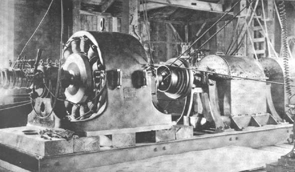
| |||
| Plate I. Generator and Waterwheels in Operation. |
Water-Power Plant.
An excellent water power was found in a mountain stream on the north slope of Castle Peak, in the Sierra Nevada, known as Green Creek, and forming one of the chief sources of the East Walker River. This stream carries 400 in. of water during the dry season, and ten times that amount during the time of melting snows.
An old ditch was cleared out and rebuilt for a length of 4,570 ft., and a site was selected for a power-house 355 ft. vertically below its lower end. The ditch was made larger than necessary for power purposes alone, with the object of supplying other parties, when there was an excess of water.
The maps, Figs. 1 and 2, give the data with regard to the ditch and pipe; and Figs. 3 and 4 show the connecting flume, pressure-tank, and waste-weirs. The arrangement of the screen adopted, while it occasions a loss of head of a couple of feet, is greatly to be recommended where "anchor" and slush-ice form in a ditch during cold weather.
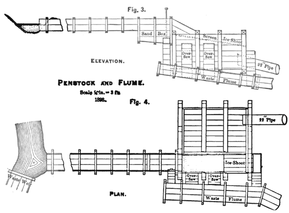 |
| Figs. 3 and 4 Penstock and Flume |
The pipe is of large diameter, in order to permit subsequent enlargement of the plant, and also to reduce loss of head by friction. It is fitted with three 2 1/2 in. air valves, to prevent collapse in case of sudden rupture, and is anchored at proper intervals with straps of 1 1/4 in. round iron. The slip-joints extend to a vertical head of 220 ft., the remainder of the pipe being laid with collar-and-sleeve lead joints.
The pipe leads into a receiver 40 in. in diameter and 9 1/2 ft. long, from which four taper-pipes lead the water, under pressure of 152 Ibs. per square inch, to as many 21 in. Pelton waterwheels, each wheel being fitted with two nozzles and rated at 60 horse-power under the largest sized tips of 1 1/8 in. diameter.
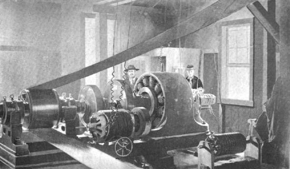
The speed of the wheels is 860 to 870 revolutions, and their shaft is connected by an insulated rigid coupling to the armature shaft of a 120 K.-W. A. C. generator. Plate I shows the generator and waterwheels in operation.
Power-House.
The accompanying plan (Fig. 5) shows the arrangement of the plant, one of the most interesting features of which is the water-governor formerly known as the "Doolittle," and now called the Pelton differential governor (Figs. 6 and 7). It operates butterfly-valves placed in the 5 in. pipes between the gate-valves and the diverging nozzles; and though this form of valve invariably "throttles" the water to a greater or less extent (according to the position of the valve), it is a most satisfactory way of controlling the power where the same is ample, and the loss due to this cause is of slight consequence. The governor operates as follows: Two 18 in. pulleys revolve loosely and in opposite directions on a shaft, one being driven from the waterwheel shaft and the other by a No. 2 Pelton motor. These pulleys have gears on their hubs which mesh into two other gear-wheels carried on an axis at right angles to the shaft and keyed fast to the latter. Beyond these wheels is a pinion, loose on the shaft and with ratchet-teeth cut in opposite directions on either side of its hub. Into these ratchet-teeth mesh corresponding circular ratchets, which are keyed to the shaft but free to move longitudinally along the same, and are thrown in or out of gear by a short lever and spring. The pinion engages a sector, which is fastened to the rod and levers that operate the butterfly-valves, and on the same rod is a hand-lever, by means of which the valves may also be opened or closed by simply throw ing out of mesh the circular ratchets alluded to and thereby detaching the governor. It is evident that when the two pulleys are revolving in opposite directions at exactly the same rate of speed, there will be no motion of the central gear-shaft, and none will be communicated to the pinion and sector and thence to the valves, to open or close them; while, on the other hand, a difference in speed of these pulleys will have the opposite effect. The belts driving them are therefore so arranged that a decrease in speed of the waterwheels will open the valves, and an increase will close them.
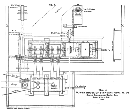 |
| Fig. 5 Plan of Power House of Standard Consolidated Mining Co. |
In starting up from rest, the governor is detached by throwing out the springs on the ratchets, and the valves are operated by the hand-lever. After the wheels are at normal speed and the load is on, the ratchets are sprung into gear with the pinion, and the governor takes care of any and all variations, even to a complete throwing off of the load by pulling the main-current plug-switch at Bodie. The speed of the governor-pulleys, as first designed, was 60 revolutions. This was found to be too slow, and it was increased to 180 revolutions with most beneficial effects, developing a greater sensitiveness to small changes of load, and much quicker action, especially when all the load was thrown off at once. In the latter case, the increase in speed of the waterwheels did not at any time exceed 12 per cent before the governor began to close the valves.
It was further found necessary to furnish a constant resistance for the water motor that drives one side of the governor, to work against. In the original plan this was to be done-by the exciter which furnishes current for the fields of the generator; but on trial it appeared that the load on the exciter was too variable, and at times too great for the little motor to take care of. The exciter was then placed so that it could be driven by either a larger size (No. 3) motor or by the waterwheel shaft-coupling (see plan of power-house); and a fly-wheel of about 1,500 Ibs. weight was set to be driven by the smaller motor and insure its constant speed.
The great drawback to the use of water power for the generation of electricity has hitherto been the lack of a good water-governor, sufficiently sensitive and quick-acting to insure the vital factor of constant speed without bringing dangerous strain on the water pipe. In fact, in the Westinghouse plant at Telluride, and in several others of which the writer is aware, the "one-man automatic regulator" had to be used; i.e., a man sat with his hand on the lever of a deflecting nozzle and his eye fixed on a voltmeter or a techometer. The above-described governor is so great an improvement over this system that its operation has been given in detail.
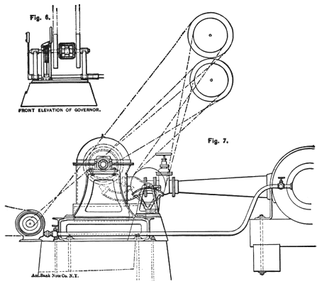 |
| Figs. 6 and 7 End Elevation of Water Wheels |
The generator is a Westinghouse 120 K.-W. constant-potential twelve-pole machine, and its armature-shaft is attached to that of the waterwheels by a rigid coupling, insulated by a disk of hard rubber one inch thick, and projecting one inch beyond the flanges, while the bolts are surrounded by bushings and washers of insulating-fiber.
The initial current in the lower half of each field-coil, or the winding nearest the armature, is instilled by means of a type "G" D. C. exciter. The secondary winding, on the armature-spokes of the dynamo, generates current when the machine is under load, which is led to a twelve-bar commutator on the armature-shaft and thence to the compensating-winding which occupies the upper half of each field-bobbin.
As the load on the generator increases, more current flows through its armature-coils, and through a primary winding on the armature-spokes, thereby inducing, in the secondary winding, a heavier current, which, being led to the magnetic field as described, proportionately strengthens the same. When the generator is running without load, there being little or no current in its armature-coils, none is induced in the secondary winding, and the compensating-winding on the fields is without magnetic effect until the latter is required by work to be performed.
The potential of the generator under full load is 3,530 volts, but at present it is operating with about 3,390. The exciter carries a voltage of 105 to 112. A "D. C." voltmeter, recently placed on the switch-board to the left of the ground-detector and above the small rheostat, is in the main circuit of the exciter, recording the tension of its current and serving as a speed indicator when the machine is driven by the No. 3 motor. This is not necessary when driving from the wheel-shaft, as is sometimes done in winter, when pieces of ice give trouble in the small nozzle of the motor.
| |||
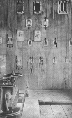
| Plate II. Generator Switch-Board at Power-House. (Generator in Operation, Exciter in Foreground, Choke-Coils and Gap-Lightning-Arresters on Separate Board. |
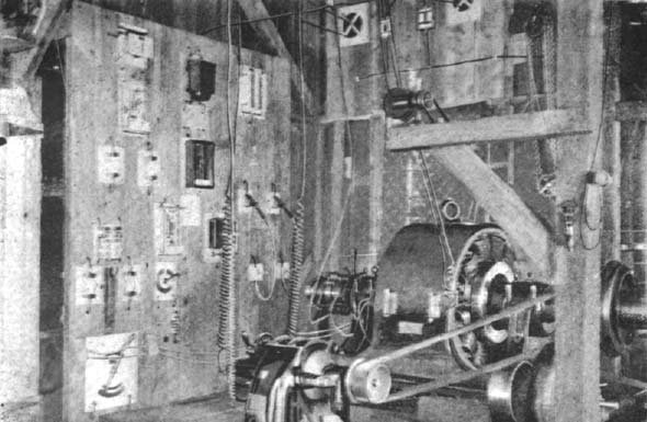
Plate II shows the generator switch-board at the power-house. The generator current is led from the collector-rings on the extreme end of the armature-shaft to the plug-sockets on the switch-board; and when the line-plugs are in these, the current follows the line to two similar sockets on the motor switch-board. The small converter in the upper middle of the switch-board has a transforming ratio of 30 to 1. Its primary coil is attached to the main-current wires from the generator, and its secondary to the A. C. voltmeter, immediately below it. A potential of 113 volts on the voltmeter is therefore equivalent to 3,390 on the dynamo current, which is the tension under normal load. The voltmeter does not, however, read 113 volts, but records 100 to 102 volts, the difference being due to the compensator (the instrument shown in the upper left-hand corner of the switch-board and connected with the voltmeter), the object being to reduce the reading by an amount about equal to the line-loss.
This loss is estimated at 15 per cent under maximum load, and is but from 8 to 10 per cent under normal load, as will be shown later on.
The ammeter, and just below it the aluminum fuses, all of which are in the main circuit, are shown to the left of the voltmeter in the view of the generator switch-board.
Immediately to the left of the main-line plug-switches is the ground-detector with two lamps, one for each leg of the line, and each lamp with its converter behind it.
A press-button below the lamps makes the necessary connection with a ground wire. Without this connection made, the lamps show a red light on the filaments, due to the difference in potential of the two sides of the line; and should a " ground " occur on either leg of the wire-line, the corresponding lamp immediately burns at full candle power, while the other lamp proportionately diminishes.
The two-pole jaw-switch to the left of the switch-board is in the circuit from the exciter to the generator-fields, as are also the two fuses and the rheostat immediately below it. The small rheostat to the right of the fuse-blocks and the single-pole switch below it are in the shunt field-circuit of the exciter. By means of these two rheostats the potential of the generator is governed and the voltmeter kept at its proper reading, the large rheostat in the exciter and generator field-circuit permitting a quick regulation over a wide range, and the shunt-rheostat a finer and closer adjustment of the voltage.
When starting up the plant one attendant stands at the lever, controlling the admission of water to the wheels through the butterfly-valves, and the other at the switch-board, handling these two rheostats (most of the regulation is done by the large one), until the motor is in synchronism and at work, when the governor is thrown into gear, the voltage is finally adjusted, and the mechanism is then practically self-regulating for all ordinary changes of load. If, for instance, ten of the twenty stamps are to be hung up, or any or all of the eight continuous-pans in the mill are to be stopped, it is never necessary first to give word to the attendant at the power-house. The governor takes charge of such changes, even to the entire throwing off of the load, as before remarked. All the bearings of the generator and water wheel shafts and of the exciter are self-oiling. The attendant has merely to keep on the qui vive and see that all is running smoothly. Any change in tone of the hum of the dynamo warns him at once of a change of conditions, the tone rising or falling according as the speed increases or diminishes, though ever so slightly.
To insure the all-important factor of constant speed, a techometer, registering to 1,200 revolutions, is belted to the water wheel and dynamo shaft. Its dial faces the waterwheels, so that the attendant at the valve lever can readily maintain a uniform speed during the operation of " synchronizing" the motor and starting the mill, at which time the load is constantly varying.
| |||
| Plate III. Power-House at Green Creek. |
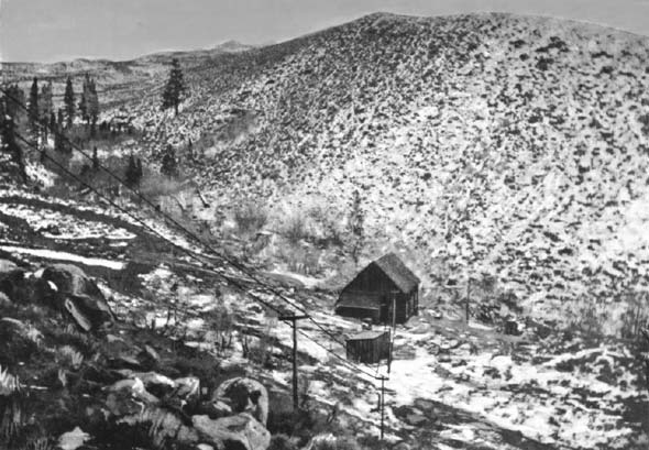
In front of the jaw-switch on the switch-board there will be noticed, in the view of the latter, a steel spring, and also two cords attached to the handle of the large rheostat. These cords are led around the side of the building to the attendant's place at the valve-lever, as is also the one that releases the catch of the spring. A pull on these cords opens the exciter main-circuit instantly, and puts in the entire resistance-box, thereby "killing" the fields of the generator and preventing any dangerous rise in electro-motive force, should the load be suddenly thrown off by a break in the wire-line, or other accident causing a sudden increase in the speed of the armature shaft. It should be explained that this arrangement was devised by the writer, before the speed of the governor was trebled, the constant-resistance fly-wheel was put in and other changes were made, giving more sensitive and perfect control of the water power; and it is left in place because it might still be of use in case of emergency. The power-house is lit by a small 10-light converter attached to the generator-circuit, and when the generator is not in operation, by current from the exciter. Plate III shows the power-house at Green Creek.
Wire-Line.
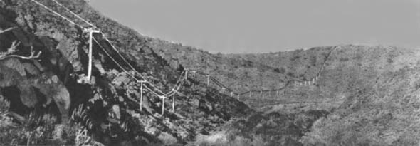
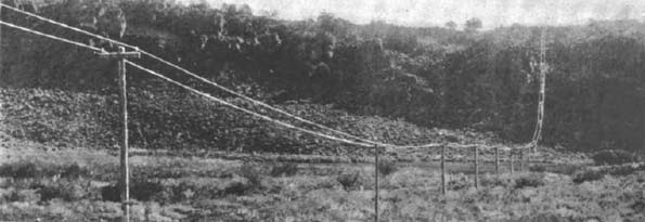
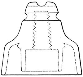
The length of the line is 67,760 ft., or 12.46 miles. The poles are of round tamarack timber, 21 ft. long, 6 in. in diameter at the top, set 4 ft. in the ground; poles 25 ft. long being used through the town, and along the line wherever there is danger of deep snowdrifts. They are placed 100 ft. apart, and fitted each with a 4 by 6 in. cross-arm, boxed into the pole, and held by one bolt and one lag-screw. The accompanying sketch (Fig. 8) shows the detail. The object of chamfering the ends of the cross-arms is to leave less room for the lodging of snow under the insulator.
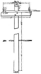 |
| Fig. 8 |
The line crosses extremely rough country, not 500 yds. of which is level beyond the town limits. Most of the ground is very rocky, over 500 Ibs. of dynamite being used in blasting the pole-holes. Plates IV and V are views along the line in summer.
| |||
| Plate IV. Summer View on Pole-Line, Looking East, 10 Miles From Bodie. |
| |||
| Plate V. Summer View on Pole-Line, Looking West, 10 Miles From Bodie. |
The wire is of No. 1 (B. & S.) gauge, soft-drawn bare copper, and is attached to standard, double-petticoat, deep-groove glass insulators (Fig. 10) carried on Klein patent iron pins (Fig. 9). The distance between the wires is 3 ft. 8 in., and there are over 16.5 tons of copper in the line. The only objection found to the iron pins is their liability to be withdrawn from the cross-arm during a gale of wind, whenever there is an upward pull on the wire. To obviate this a number of pins were drilled with an 1/8 in. hole near the end, and in all such places these were used, and held firm by driving a wire nail through them.
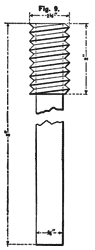 |
| Fig. 9. Klein Patent Iron Pin. Lead Thread. |
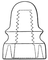 |
| Fig. 10. Deep Groove Double-Petticoat Glass Insulator. Half Size. |
The wire was first attached to the insulators by tie-wires of No. 10 galvanized iron wire. Later it was found advisable to insulate the line-wire at the insulators, and for this purpose ordinary sheet-rubber 1/8 in. thick, such as is used for gaskets, was cut into strips 1.5 in. wide and 12 in. long. These were wound spirally about the wire and held in place by two close wrappings of Manson's tape. The whole was then well daubed with asphalt paint, and the insulated wire re-attached to the insulators by tie-wires of No. 6 weather-proof copper wire.
 |
| Fig. 11. Westinghouse "Pomona" Double-Petticoat Glass Insulator. Half Size. |
The line crosses a number of very steep ridges (from 300 to 800 ft. in height), and on these the wire necessarily pulls heavily on the top pole, and especially on its pins and insulators. In all such places the ordinary double-petticoat insulators were replaced by the large "Pomona" insulator (Fig. 11), on which the wire is carried in a groove across the top, and its weight is therefore directly down upon and in line with the center of the pin.
The line has given no trouble whatsoever, and has carried the high potential of 3,000 volts without a leak, even during a severe storm of ten hours' duration, the rain changing to sleet and ice toward the end; but this severe test, it must be admitted, occurred after the wire had been wrapped at the insulators as described. In fact, one of the chief objects of this insulation was to render the line proof against just such a storm as this. Snow-storms have no effect whatever. (See Fig. 12.)
Motor-Room
The motor that drives the stamp mill of the Standard Consolidated Mining Company at Bodie is an A. C. synchronous constant-potential machine of 120 horse-power. The mill contains twenty 750 lb. stamps, four wide-belt (6 ft.) Frue vanners, eight continuous-process amalgamating-pans (two of which are constantly grinding), three settlers, one agitator, one pan and settler devoted to the amalgamation of concentrates, a bucket elevator, a worm-gear hoist, and a rock-crusher. In order to determine accurately the capacity of motor required, a number of cards were taken with the Tabor indicator from the 20 by 36 inch steam engine that drove the mill, showing an average of 90 and a maximum of 101 1/2 horse-power.
The fields of the motor are self-exciting through a secondary winding on the teeth of the armature, the current being led to a twelve-bar commutator similar to that on the generator. In fact, the motor is almost identical with the generator, the chief difference being in the compensating-winding on the field-bobbins of the latter.
| |||
| Plate VI. Motor in Operation. Standard Con's Mill. |
On the armature-shaft of the motor is a friction-wheel, and beyond this a clutch, which is used to set in motion the driving-pulley and the machinery of the mill. On the same bed-plate with the motor is a small 10 horse-power Tesla starting-motor, with a wooden pulley on its shaft, that is brought to bear against the friction-wheel mentioned, by means of a screw and hand-wheel. This Tesla motor consists simply of field coils and an armature; it has neither brushes, nor commutator, nor sliding contacts of any kind. The alternating current is led directly into the fields, the stationary element, the coils of which, being connected in series, produce a rotating magnetic field, in that each pole is alternately positive and negative. The starting-torque of the armature is, in consequence, very low, and it has to receive several rapid turns by hand before putting on the current, after which it generally runs up to normal speed (1,660 revolutions) within a minute. Plate VI shows the motor in operation.
| |||
| Plate VII. Motor Switch-Board. |
Turning our attention to the switch-board, shown in Plate VII, the two plugs in the sockets on the right of the board are the line-plugs, and the two to the left of them, in their rests, are the starting-motor plugs. When the line-plugs are in their sockets the current is led directly to the top of the upper jaw-switch, and this switch is never closed until the machines are in synchronism. The wires from the bottom of this switch lead directly to the collector-rings on the armature-shaft of the motor.
In the upper right-hand of the board is the Wurts lightning-arrester, consisting of 22 spools, 11 on a side, separated each by a distance of 1/32 in. Both legs of the wire-line are attached to the arrester, one on each side at the top, while the ground-wire leads from the bottom spools to a water-pipe in the earth. The spools are made of a patent non-arcing metal, and the dynamo current will therefore not follow the path through them made by a discharge of high-tension atmospheric electricity. The properties of this alloy are such that oxides of the metals are generated by the passage of lightning and not vapor of the metal itself.
To the left of this instrument are two converters of the ratio of 30 to 1, filled with paraffine oil. The primary coil of the right-hand one is connected to the main line just above the plug-sockets, and that of the left-hand converter is connected to the motor-circuit, i. e., the wires leading from the collector-rings on the armature-shaft to the bottom of the upper jaw-switch; it being understood that the motor acts as a generator when being driven by the starting-motor.
The secondary of the line-current converter goes to the top posts, marked G, of the synchronizer (the marble plate with four lamps on it to the extreme left of the board), one leg being first carried through the right-hand side of the lower jaw-switch. When the line-plugs are in, therefore, and this switch is closed, the top light of the synchronizer will always be burning while the generator at the power-house is in operation.
The secondary of the motor-current converter is carried directly to the bottom posts, marked M, of the synchronizer, the two middle lamps of which are connected in series with the motor and generator currents.
The field-circuit of the motor is carried to the switch-board, and in it are placed the large rheostat, the left-hand ammeter, and the left-hand side of the lower jaw-switch. The closing of this switch and an adjustment of the rheostat will therefore cause the lower light on the synchronizer to burn whenever the motor is being run as a generator, as is the case when it is being driven by the starting-motor. The aluminum fuses showing below the converters are in the main line before it reaches the jaw-switch, as is also the ammeter just below them, which instrument should, and does, record the same volume of current as its fellow in the power-house.
To start the motor requires two men, one to handle the starting-motor and the other at the switch-board. The line-plugs are put in, which leads the main current to the top of the synchronizing-switch, and the lower jaw-switch is thrown in, which closes the field-circuit of the motor, and the secondary of the main-line or generator converter, thereby lighting the upper lamp of the synchronizer. The armature of the starting-motor is turned a few times by hand, and the two left-hand plugs are then pushed into their sockets, leading the current from the main line to the fields of this motor.
Immediately upon doing this, the main-current ammeter records 30 amperes, and the needle stays at this reading until the starting-motor is up to speed, when it drops quickly to 18 to 20 amperes. It takes from fifty to seventy seconds for the starting-motor to reach full speed, after which its friction-wheel is brought to bear against that of the main motor, and the armature of the latter begins to revolve. During .this time the synchronizing-switch (the upper jaw-switch) is open, and all the resistance-coils of the rheostat are left in the field-circuit, in order that the armature may more easily be brought up to speed, by preventing the flow of current in the same.
As soon as the armature is above speed, about two thirds of the rheostat is thrown out, permitting 40 or 50 amperes of current to flow, and the lower lamp of the synchronizer to burn. The pushing onto its button of the little switch on the bottom of the synchronizer now connects the two central lamps in series with the motor- and the generatorcurrents, and they begin to flash in accordance with the phases, and therefore the speeds, of the two machines. As the speed of the motor approaches that of the generator, the wave-phases come nearer coincidence, and these lamps brighten and darken almost simultaneously.
The attendant stands with one hand on the rheostat and the other on the open jaw-switch, watching these waves of light intently, and just as the two lamps darken in unison, he throws in the switch and pulls one of the starting-motor plugs. The lamps only remain "out" for a second or less, while the speeds are together, and then flash up brightly again as the motor speed drops off; there is therefore but a fraction of a second during which the jaw-switch should be closed, though this time can be lengthened slightly by a proper handling of the starting-motor.
If this switch has been thrown in at the right moment, the series lights remain "out," while the top and bottom, or "pilot" lights, burn brightly, and so continue all the while the machines are in operation. If the switch is thrown in a second or so too soon, the main-current ammeter will fly up to 40 or 45 amperes, and quickly drop down to less than 10 as the motor speed decreases, and it falls into step with the generator, while the series-lamps will remain dark, and the pilot-lamps burn as usual. On the other hand, if it is closed several seconds too soon, or a fraction of a second too late, it is impossible for the machines to get into synchronism. In such event all the lights on the synchronizer go out at once, and a heavy flow of current sets in, the main ammeter showing 45 amperes, which is as high as it can record. By the extinction of the lights the attendant sees at once that he has missed the synchronizing-point, and immediately pulls the main-line plug, opens the jaw-switch, and starts over again. The second trial, however, will not consume as much time as the first, since the starting-motor is still revolving at a high speed, and more quickly comes up to its normal rate, while the motor-armature is also running yet at several hundred revolutions per minute.
This very rarely happens, especially since the addition in March last of an acoustic synchronizer to the phase-lamp device. This instrument emits a sound, the pulsations of which are very rapid at first, the interval between them growing longer as the machines approach equal speed, and settling into a steady hum at the moment of synchronism.
It will be noticed that in order to break the circuit and stop the motor it is necessary to pull the line-plug, on doing which a brilliant arc, sometimes 2 ft. in length, if 25 amperes are flowing, follows out from the socket to the plug-tip. Any attempt to open the jaw-switch while the line-plugs are in would doubtless result in the death of whomsoever tried it, since the distance is too short in which to break the arc, and the current would likely follow down the arm in spite of one's standing on an insulated floor. These floors are used around both generator and motor, and in front of both switch-boards.
The entire operation of starting up the motor from a state of rest occupies from three to five minutes, and when once in synchronism, the clutch can be thrown in and the mill shafting brought to normal speed in from one to two minutes more, after which the load may be thrown on as fast as desired without the least danger of pulling the motor out of synchronism. The clutch is always thrown in slowly in order to prevent too heavy a flow of current, and consequent sparking of the commutator brushes.
By means of a single counter-shaft, fitted with self-oiling boxes, the high speed of the motor (860 revolutions) is reduced to the necessary 80 revolutions of the battery line-shaft, the reductions being 2 ft. to 8 ft., and 3 ft. to 8 ft. Light steel-rim balanced pulleys are used, and an endless 16 in. double leather belt runs from the motor to the first 8 ft. pulley. The speed of this belt is 5,400 ft. per minute, and it is kept tight by levers which, acting through screws, move the entire motor and its bed-plate along four grooved, cast-iron slides.
The motor is separated from the underlying brick foundation by means of 8 by 10 in. timbers, which are bolted to the latter and covered by three layers of 1 in. boards; and to this wood insulation the slides referred to are fastened by lag-screws that pass through the boards into the timbers. The generator is insulated from the I-beams that carry both it and the waterwheels, by timbers 54 in. thick, to which it is likewise secured by lag-screws.
The mill and offices of the company are lit by 100-volt incandescent lamps, taking current from a large 100-light converter, ratio 30 to 1, which is attached to the main line in the motor-room, before it reaches the switch-board. The light is very satisfactory, even to read or write by, although at times the lamps nicker slightly, due to small changes of load. This variation of intensity is, of course, unavoidable where the lighting current is taken direct from a power circuit; but, in the present case at least, is not sufficiently noticeable to cause inconvenience.
During normal operation of the plant, the field-ammeter of the motor is, by means of the rheostat, kept steadily at 52 amperes, while with full load on the mill the main-current ammeter registers from 23 to 25 amperes. The needle oscillates over a range of 4 to 6 amperes, showing considerable variation of load, due undoubtedly to slipping of the belts, unequal resistance of .the grinding-pans, rock-crusher, etc., so that it is difficult to read this ammeter closely, either at the generator or at the motor.
The average amperes of current can be very closely approximated, however, as was done in the tabulated readings given below, which were taken with the object of determining the line-loss, and with the aid of Mr. H. M. Reed, the engineer of the Westinghouse Electric and Manufacturing Company, who installed and first operated this apparatus.
The readings were taken simultaneously at power-house and motor-room, by means of the telephone, and the figures given are the averages of five or six consecutive observations. There being no voltmeter on the motor switch-board, a Weston portable voltmeter was used, the wires being attached to the lower posts on the synchronizer.
The table is merely a rough approximation of the efficiency of the transmission, there being no instruments at hand for close work, such as the measurement of the wheel-shaft energy, or of that given out at the motor-pulley. The efficiency of these machines, namely, of the generator, 95.5 per cent, and of the motor, 93.9 per cent, was determined by Mr. Fred. A. Davis, electrical engineer of the Westinghouse Electric and Manufacturing Company, in charge of the plant. It will be noticed from the table that the line-loss is very light, and also that as the dynamo and motor approach their rated capacity, the efficiency of the transmission increases.
 |
