[Trade Journal]
Publication: The Cornell Civil Engineer
Ithaca, NY, United States
vol. 18, no. 3, p. 86-90, col. 1
THE ELECTRIFICATION OF THE WEST SHORE RAILROAD FROM UTICA TO SYRACUSE.
HENRY G. THROOP, '05.
The work of electrifying the West Shore Railroad from the City Line of Syracuse to the Genesee St. crossing at Utica, N. Y., has been completed by the Oneida Railway Co., a corporation formed primarily for the construction and operation of a Street Railway in Oneida, N. Y. It was originally planned to use an overhead system employing the catenary type of suspension for the trolley wire and steel overhead bridges for support, these bridges being spaced 300 feet apart along the right of way. Due to the fact that this type of construction limited the width of trackage, required a long time to construct, and other reasons, it was decided to install the Sprague-Wilgus under-running contact rail system.
Erection of third rail was commenced August 28th, 1906, and about 70 miles of rail was erected by December 20th of that year. Work was again opened on March 20th, 1907, and the remaining 35 miles of electrification was completed by May 21st. Operation of the road for passenger traffic was commenced June 16th, 1907, and has been continuous since that date.
The installation of this third rail system was carried out under three general divisions of the work, viz: The erection of a High Tension Transmission line from Clark's Mills to Manlius Centre, a distance of 32.005 miles. The erection of four Substations, one at Clark's Mills, one at a point 1.5 miles West of Vernon, one 2.2 miles west of Canastota, and one at Manlius Centre, The installation of the third rail between the City line of Syracuse and Genesee St., Utica, approximates 44 1/2 miles of road or 105.756 miles of track. The erection of the Transmission line and substations was carried out by contractors while the installation of the Third Rail was completed by the construction forces of the Oneida Railway Co.
Transmission Line.
The electrical power used on this line is generated at a power house in Utica from which it is transmitted in the form of three-phase alternating current at a pressure of 60,000 volts to Substation No. 1 at Clark's Mills, a distance of 7 1/2 miles. After passing through Substation No. 1 this current, still at 60,000 volts, is carried through the three remaining substations to Manlius Centre over the Transmission line of the Oneida Railway Co.
This line consists of 392 steel towers formed from angles and rods and varying in height from 39 feet to 63 feet in increments of 6 feet with a standard spacing of 480 feet along the right of way of the West Shore R. R. The four foundation angles of these towers were riveted to two sets of angle iron frames which formed the reinforcement for two concrete footing blocks, the footing blocks being placed with their longer axis parallel to the direction of the line and 5 feet below ground surface. The angles of the tower which extended down into these footings were surrounded to the level of the ground surface with a six inch column of concrete cast in place, an ordinary stove pipe being used for a form.
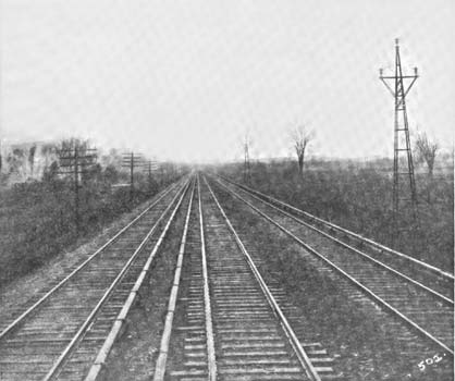
| |||
| View Showing Three Track Section, Third Rail and Transmission Line Towers. |
The 39 foot towers were assembled in the contractor's shop and brought to the place of erection on flat cars, towers over 39 feet in height being delivered in two sections. Erection was made with an ordinary gin pole and a team of horses, 12 towers per gang being the daily rate of progress. These towers support three No. 0 seven-stranded hard drawn copper cables having a tensile strength of 45,000 pounds per square inch. The cables are mounted on porcelain insulators so set that the cables are supported at points forming the verticus of an equilateral triangle whose sides are seven feet. The cables are tied to the insulators by a special double tie, twenty feet of No. 6 copper wire being used to each insulator. Not over 6 feet difference in elevation between the tops of any two adjacent towers was allowed, and the cables cleared all buildings, trees or other lines by at least 10 feet both vertically and horizontally. On curves the standard spacing of towers was shortened so as not to bring an angle of over 6° on any one insulator. On towers adjacent to highways and on the shorter curves an iron clamp was substituted for tie wire for holding the cables to the insulators.
In stringing the cable an allowance for sag was made of 12 feet for a span of 480 feet and a temperature of 32° F., shorter spans being adjusted accordingly. Each tower was grounded to a copper plate one foot square buried five feet under ground and surrounded with charcoal, a No. 0 wire attached to the plate being bolted to one of the tower angles.
Substations.
The four Substations are identical with the exception that the last one at Manlius Centre has no provision for an outgoing line. The spacing between stations averages 10 1/2 miles, the first and fourth stations being 6 miles from the ends of the road. The buildings are of brick and concrete with litholite trimmings and absolutely fireproof. 47' 2" by 63' 8" in plan and 37' 8" high. The equipment consists of two 300 Kw. 40 cycle rotary converters with the necessary transformers, oil switches, etc., for changing the current from 60,000 volts a. c. to a line voltage of 600 d. c. Provision is made for the installation of a third rotary should an increased use of power render this necessary. Particular attention was given to the provision of adequate protection for the high tension wiring, all 60,000 volt conductors back of the transformers being placed in separate brick and concrete compartments. A large room is provided in one end of the buildings for the storage of third rail and high tension line supplies. A subway under the main floor allows the proper space for the passage of cables from the machines to the switch board and the conductors which convey the current out to the third rail.
Third Rail.
The Third Rail is a 70 pound Lackawanna Steel Co. 1906 bullhead rail, of the same chemical composition as the track rails of that date made by the same Company. Long ties for the support of the third rail were placed in the tracks; spaced 11 feet centre, to centre and so arranged as to avoid coming under track joints. These ties are of hard pine 9' 6" long and 7" by 9" in section. One end is placed in line with the ends of the standard 8' ties the other extending out from the track rail a sufficient distance to allow the third rail to be so placed as to bring its centre line 32" from the gauge line of the nearer track rail. The third rail is placed on the high side of all curves to provide greater clearance for wide equipment which may pass over the road in steam trains.
A cast iron bracket is lag screwed to each third rail tie and this supports a pair of insulator blocks which grip the third rail and are held together by a special hookbolt passing through the top of the bracket and over the outer insulator block. Both porcelain and wooden insulators are used. When erected the lower or contact face of the third rail is held 2 3/4 inches above the top of the track rails. A wooden cover in three piece sections 10' 6" long is fitted over the rail and held in place by 3 1/2 drive screws. A patented fibre cover formed to the shape of the third rail is used on some ten miles of track. This cover is composed of wood pulp impregnated with linseed oil.
The third rails are bolted together by two bolt strap plates. In addition to the ordinary allowance for expansion of the rails an extra space of 2 inches is placed once in each one thousand feet. The joints in the rails are bonded with two copper bonds each of a capacity of 500,000 circular mills soldered to the upper ball of the rails. Current is carried under special work and highway crossings by a 1,000,000 circular mill copper cable, rubber insulated and lead covered, placed in a 3" galvanized iron pipe duct. The ends of this cable are divided and soldered to terminals which are in turn both soldered and bolted to the web of the third rail.
All ends of third rail are provided with a cast iron incline point which allows the contact shoe on the cars to pass under the rail without a noticeable blow. Track rails are bonded with a 4-0 copper bond, either compression terminal or soldered, only 1000 of the latter type being installed for experimental purposes.
Operation.
Electric passenger cars of 40 tons weigh, 49 feet in length, with a seating capacity of 52, are operated over this line at a maximum speed of 55 miles an hour. Local cars, averaging 20 stops per single trip, make the distance from the center of Utica to the centre of Syracuse in one hour and fifty minutes, while limited trains cover the same distance with two stops in one hour and twenty eight minutes. Two car trains are also operated when traffic requires. An average of sixty electric and ten steam trains pass over the line daily where previous to electrification only some ten steam trains covered the route every twenty four hours.
