[Trade Journal]
Publication: The Journal of Electricity, Power and Gas
San Francisco, CA, United States
vol. 11, no. 5, p. 97-98, col. 1-2
·
·
[Missing text]
·
·
dinal channel 3 inches wide with walls each braced by six 5-inch ribs, is cast into the saddle base, and in this channel are placed five cast-iron sheaves supported on 1-1/6-inch steel pinions the centers of which pinions are on an arc with an 8-foot radius. These sheaves have a diameter of 5-7/8 inches by an extreme width of 3 inches, and they are galvanizedas in fact are all cast-iron pieces exposed to the weather.
| |||
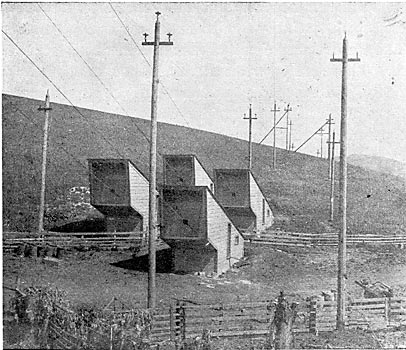
| The Four Anchorages Behind the Leaning Tower. |
An extreme variation in temperature of 60° F. may possibly occur at Carquinez, which would cause a variation of 5 feet in the sag and which in turn would cause a travel of approximately two inches to occur in the cables running over the sheaves of the main tower.
Individual anchorages, well separated, are provided for the concrete blocks are crossed channels and plates from which extend steel eyebolts with pin connections, first, to two sets of steel car springs, then a turnbuckle, then two tandem yokes connecting with heavy micanite insulators in copper cases containing transformer oil; and lastly, a 24-inch sheave around which the cable is turned and secured with clamps and clips. Outlines of the above are given in the drawing last referred to.
| |||
| How the Cables Enter Their Anchorages. |
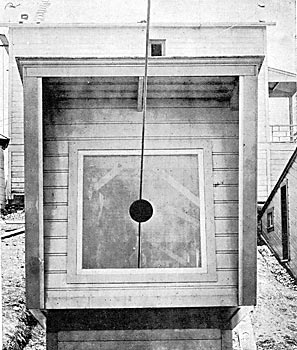
As with the saddles, all iron parts of the anchorages are galvanized, and the entire work is characterized by the utmost stability and thoroughness. Some idea of the character and dimensions of the strain insulators used will be obtained from a description of the stirrups and rings which support them. Each stirrup is made of a wrought-iron bar inches square forged into the shape shown in the drawing giving the general design of the connection details of the anchorages. The width of the stirrup in the clear is 13 inches, and its length from yoke to foot is 4o inches. Upon the tread or foot of the stirrup is placed a cast-iron ring 10 ½ inches in outside diameter by an inside diameter of 6 inches with a length of 5 inches. Holes 1-3/4 inches square by 3/4 inch deep are cast in diametrically opposite points to give footing for the treads of the stirrups, and on the opposite or upper side of the ring is placed a micanite washer some 5 inches thick, with channels cut in its outer surface to increase the leakage surface. A final cast-iron washer with nut and check-nut completes the equipment with the exception that a copper tank filled with transformer oil encloses all, and a funnel-shaped porcelain placed as shown in the halftone on the next page gives added surface that tends to prevent leakage. Each anchorage is enclosed in an independent housing which is illustrated in exterior and interior views by the accompanying reproductions from photographs--the cable entering by way of a circular hole six inches in diameter cut through the center of the plate glass that is placed in the end of the housing. The cables are "dead-ended at the anchorages, and power is delivered to or taken from them by means of taps spliced on to them near the saddles of the north and south towers respectively. These taps come only from the substations at the two towers named, and of the four cables that have been erected, but three are ever in use at one time, the fourth being always held in reserve. Moreover, the cleaning, overhauling or repairing of all the cables in rotation is possible at any time when one is in reserve.
The cables are of solid plow steel with a solid steel core. There are 19 wires in the twisted stand, including the core, and the made-up diameter of the strand is seven-eighths of an inch. They are arranged in suspension on the points of a rhombus having 20-foot sides, and, when examined from the towers, their rigidity is apparently absolute. Again, when viewed from the tops of the towers, the sag in the span seems to be much greater than from a lower point of observation: in fact, it looks as though it had the catenary of a long jumping-rope. This sag is obviously much greater from the south tower than from the main tower, for the former is, as stated, 80 feet higher than the latter, and the sag from the two are therefore 227 feet and 147 feet respectively. It is of interest to note, by way of comment on the perfection of the insulation of the cables, that when the cables are dead and the wind is blowing from the proper quarter, the cables become charged with static electricity so that a spark having a length of one-quarter inch or more may be drawn from them.
It is something of a paradox that the cables move less on a windy day than on a perfectly quiet one. On a quiet morning one can put his hand on the cables, when no current is on, and feel a continuous jarring movement, but a little later in the day, when the afternoon breeze is blowing, he can take hold of the same cable and find it not only free from movement, but so absolutely rigid that if one imagines he can send a wave of motion out into the span by striking the cable a blow, he has but to try it to be convinced that it is immovable.
| |||
| A Saddle Insulator Under Test. |
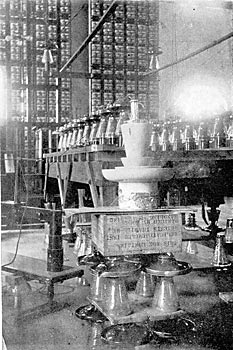
During the time in which they have been in service, they have been in operation at 40,000 volts with absolutely perfect success although subjected to one of the most severe storms that has ever been known to have occurred in their vicinity. The strain insulators were tested at 120,000 volts, and as two are used in series the factor of safety is 4 at a line potential of 60,000 volts.
| |||
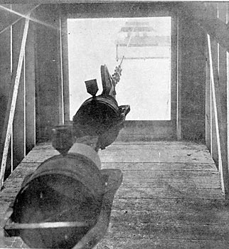
| The Cable is Anchored Through Two Strain Insulators Placed in Tandem. |
Reverting again to the mechanical features of the span, it should be stated that the problem of erecting the cables to their positions in the span was one that called for con-
·
·
[Missing text]
·
·
