[Trade Journal]
Publication: Electrical World and Engineer
New York, NY, United States
vol. 37, no. 23, p. 963-966, col. 1-2
Spanning Carquinez Straits with a High-Potential
Transmission Line.
BY R. H. STERLING.
WHEN the Bay Counties Power Company, of California, decided to extend its line from its power houses on the two branches of the Yuba River in the Sierra Nevada Mountains to find a market for its power along the shores of San Francisco Bay and in the city of Oakland, the fact was not lost sight of that such an undertaking would necessitate some features in engineering and line construction that had never before been encountered in long-distance transmission. The extensive market in sight, however, overcame any dread at the thought that there would be 140 miles to cover and miles of mountainous country and long stretches of swamp lands through which the lines would have to be built, and finally, that within 20 miles of Oakland the Straits of Carquinez intercepted the route.
| |||
| Fig. 1.--High-Potential Transmission Line Spanning Carquinez Straits. |
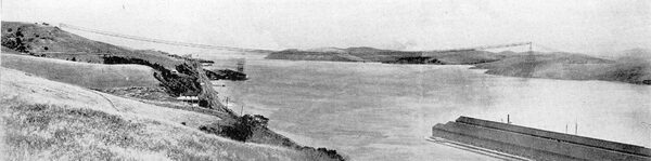
This channel is a deep, swiftly-moving waterway about 3200 ft. wide at its narrowest point, and to cross this was the first serious question for thought. Two methods were available for making this crossing, either to transform from the line voltage of 60,000 that it had been decided to adopt, down to a safe pressure for a submarine cable, and then up again to the initial voltage, or to make an aerial crossing. When the loss in these two transformations was considered it was decided to adopt the latter method, and it is the purpose of this article to describe this feature of the work in the spanning of Carquinez Straits.
| |||
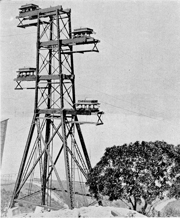
| Fig. 2.--South Tower, 65 Ft. High. |
Government requirements called for a clearance of 200 ft. above high water, so that the masts of the tallest vessels could pass safely underneath. An occasional wind velocity of 75 miles an hour occurs at times at this point, so that the features of suspension bridge construction were adopted, and the engineering details were turned over to the Pacific Construction Company, of San Francisco, which has most successfully carried out this undertaking.
| |||
| Fig. 3.--North Tower, 225 Ft. High. |
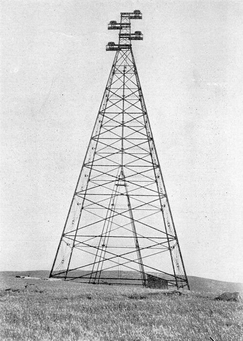
Points were located on opposite sides of the Straits where the greatest elevation of land combined with the shortest span was available, and steel towers erected. On the north side a point of land that stood 160 ft. above the water's edge was selected, and owing to the height required from the water at the center of the span and the sag necessary in the suspension to give the required factor of safety in the cable, a tower 225 ft. in height was built. On the south side, to save in height of tower, a point further back and higher up the hill was selected, that only called for a tower 65 ft. in height. This made the span from tower to tower 4427 ft., undoubtedly the longest span of the kind in the world, and when it is considered that the span of the Brooklyn bridge is but 1600 ft. between towers, some comparison can be had. The total distance from one anchorage to the other is 6200 ft.
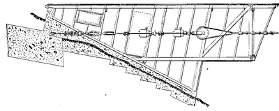
One of the most important factors in this crossing is the cable, it serving at the same time the purpose of electrical conductor and suspension cable. It is made up of 19 strands of galvanized plow steel wires, forming a cable seven-eighths of an inch in diameter and having the electrical conductivity of a No. 2 copper wire. Four of these cables were stretched so as to have one in reserve for the three-phase system in use. The breaking strain of each cable is guaranteed at 98,000 lbs., and the total weight of each span is 7080 lbs.; with a sag of 100 ft. there remains a factor of safety of 4. The cables, in suspension bridge construction, are not fastened rigidly to the towers, but pass over them on grooved rollers and thence on to the anchorage at each end, where a strain of 12 tons is exerted for each cable, the bearing down strain on the saddles at the towers being 7000 lbs. for each. The anchorages are composed of heavy concrete blocks embedded deeply in the earth with anchor bolts running through them.
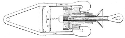 |
| Fig. 4.Detail of Strain Insulator. |
In connection with this work the writer was called upon to design the insulating details for this crossing, a description of which may be of interest.
The insulators used in this crossing are of two kinds, the saddle insulator on the towers, which support the weight of the cables, and the strain insulators that insulate the cables from the anchorages and take the entire pull of the cables. The former are composed of glazed porcelain and made by cementing together with sulphur four separate porcelain shells with heavy conical steel pin sulphured into the center one. Over this pin is slipped a tapering porcelain sleeve. The weight of one of these insulators is 75 lbs., exclusive of the pin, and measures 17 inches in diameter at the outer petticoat. Six of these insulators comprise a group to support a wooden platform in which are six deep holes that fit down over the main body of the insulators. An eave extends around the edges of the platform to protect somewhat the insulators underneath from driving rain, and a spout is arranged to carry off the accumulated water. On top of the platform is placed the cast iron saddle proper, which contains five grooved steel sheaves set in line on which the cable rests and allows for any movement due to expansion and contraction. The six saddle insulators are bolted to two heavy timbers extending out 8 ft. from the tower, thoroughly kiln dried, filled and varnished to repel moisture. These timbers present a considerable length of creepage surface, and add in no small degree to the general insulation on the towers, while the saddle insulators themselves have stood 100 and 10,000 volts under test, with one terminal connected on the outer surface and the other to the pin; and added to this, the thick wooden platforms have been boiled in paraffine.
 |
| Fig. 5.Saddle and Insulators. |
Before taking up the strain insulators it will be stated that in designing the towers the question of the cables swinging together in heavy winds was given careful consideration, and for this reason a horizontal separation of 20 ft. was provided between cables; but since being put into service it has been found that owing to the great weight for so small a wind surface presented there is no appreciable movement of the cables even in the strongest gales.
 |
| Fig. 6.--Saddle Insulators. |
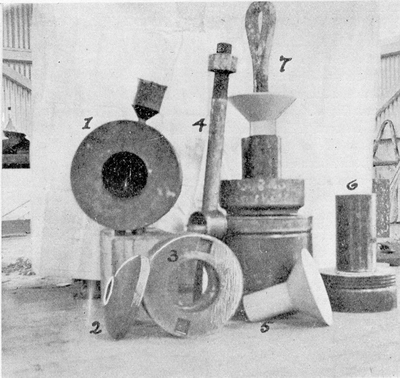 |
| Fig. 7.Strain Insulator Parts |
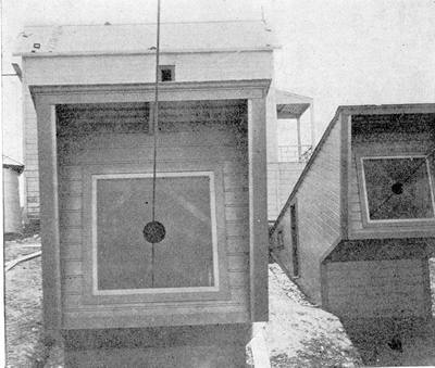 |
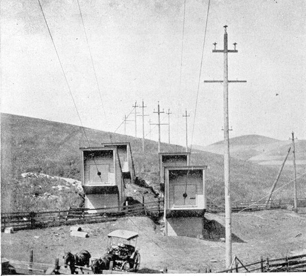
| Fig. 8.Anchor Houses, With Cables Passing Out From Strain Insulators. |
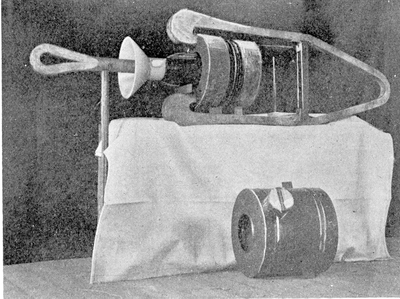 |
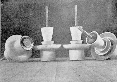
| Fig. 9.Strain Insulator Oil Tank Removed. |
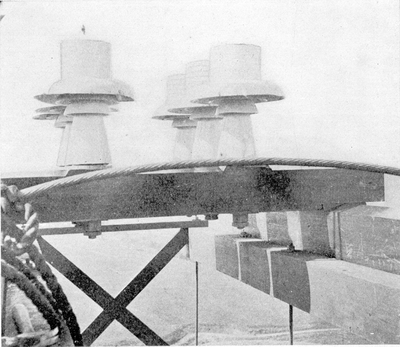 |
| Fig. 10.Six Saddle Insulators in Position. |
| |||
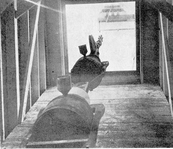
| Fig. 11.Interior of Anchor House Showing Strain Insulator Attached to Cable. |
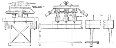
The designing of the strain insulators presented considerable difficulty. It was first decided to adopt porcelain in their construction, and the failure on the part of the manufacturer to turn out an article that was in any degree perfect mechanically, finally led to the adoption of micanite. This substance has been the salvation of the insulator, for it combines great mechanical with dialectric strength, but, unfortunately, does not possess good surface insulation; that is to say, the shellac which is used to glue the layers of mica together oxidizes and offers a low creepage surface. This defect was overcome by combining with the micanite in this insulator the advantages of oil and porcelain, using the porcelain where mechanical strength was not required.
The detailed sectional drawing and photograph of the unassembled parts will best describe the arrangement of this insulator. The conical porcelain tube here shown gives ample surface insulation between the drawbar and the steel collar corresponding to the difference of potential of the insulator, while the oil inside the copper tank acts in like service as well as to prevent arcing between opposite parts. The grooves shown on the flange of the micanite bushings are to increase the length of creepage surface, which, even in oil, is for this voltage not wholly to be relied on unless ample distance is given. The small cylinder or funnel on top of the tank is provided for filling it with oil and to inspect the oil level. While one of these strain insulators has sufficient insulation for the voltage used, it was deemed best to place two of them in series, so in case one gave out there would still remain a protection from grounding the cable.
 |
| Fig. 12.Anchorage and Shelter. |
It will, of course, be observed that no means are provided on the insulators themselves to prevent the interception of leakage to earth .due to moisture on the surface, as in the case of the petticoat in line insulators. This, owing to the position in which the insulators are placed, makes such an arrangement impossible; therefore, a shelter was built over each set, and the entrance of the cable through the end of the house provided with a large window of plate glass with a hole 9 inches in diameter through which the cable passes.
| |||
| Fig. 13.General View of Anchorage. |
Conductors are soldered to the cables just before they enter the anchor houses, and are led to the two sub-stations near by at either end of the crossing; there, by means of high-tension switches, any cable can be thrown out of service and repairs on it or on any of the insulators made, after first grounding the cable to be operated on, since the static effect is quite heavy.
The sub-stations mentioned also contain step-down transformers of 1500-kw capacity for each station from which 5000-volt current is transmitted from five to nine miles up and down each side of the Bay, where it is used for power and lighting at the various towns and manufactories on the way.
