[Trade Journal]
Publication: American Institute Of Electrical Engineers
New York, NY, United States
p. 514
(missing pages before 514 and after 522)
·
·
[Missing text]
·
·
self-induction. As a protection against lightning, a barbed iron wire of the kind extensively used for fencing cattle ranges in the West was carried upon an iron pin near each end of the upper cross arm, this wire being grounded at every fifth pole.
| |||
| Fig. 24. |
| |||
| Fig. 25. Section of Forbes Subway |
Porcelain insulators of two types, designated, respectively, the Niagara type and Type "C" were used. The pins are of locust. A section of the Type "C" insulator and pin is shown at the right in Fig. 26. The conductors are copper, having 19 strands, and weigh a little more than one pound per linear foot. Every insulator used was subjected to a puncture test of 40,000 volts, alternating, before it was put in place. The method of test is as follows: The insulators are inverted and set in a hollow iron pan which is filled with salt water to a depth of two inches. A small quantity of the salt water is poured into the pin hole of each insulator and a small metallic rod is placed vertically in the pin hole where it of course makes good contact with the brine. One pole of the alternating potential is connected to the metal rod, while the other is connected to the pan. Any weakness of the insulator is quickly manifested by a series of sparks usually followed by a breakdown of the insulator and blowing of the fine wire fuse included in the testing circuit.
| |||
| Fig. 26. |
In service the guard wires caused trouble by breaking and falling upon the charged conductors, thereby grounding and in some instances short-circuiting the latter. While neither snow nor sleet has ever been observed to adhere to the charged conductors, the guard wires of course became heavily loaded with ice, and as they were not sufficiently strong were frequently broken by weight of ice and by wind pressure. Whether they were of any practical value in mitigating the effects of lightning is an open question. I am of the opinion that they were probably of some benefit in that direction, but the interference with continuity of service which resulted from them was intolerable and they were therefore removed during the summer of 1898. Obviously, if guard wires are used either for protection against lightning or to prevent other wires falling across a power circuit, they should be of ample mechanical strength to withstand all strains to which they are liable to be subjected.
Experience also demonstrated that it was a mistake to place the three conductors constituting a circuit on the same horizontal plane and only 18 inches apart as shown at the left in Fig. 27. I may be excused for disclaiming responsibility for this arrangement in view of the fact that in 1894, acting as Electrical Engineer of the Westinghouse Company, I submitted to the Cataract Construction Company elaborate plans and specifications for a transmission line in which the three conductors constituting a circuit were triangled, the sides of the equilateral triangle being 36 inches. These plans were rejected in favor of others and the arrangement actually adopted by the company proved very tempting to mischievous or malicious boys who repeatedly short-circuited the line by throwing across it short pieces of wire which they succeeded in lodging across two or more of the conductors. The-resulting short-circuit continued to blaze along the line until the power was cut off at the Falls. The arc always traveled away from the power house. This, I presume, was due to the fact that when the short-circuit occurred the conductors affected between the power house and the point where the short-circuiting wire lay across the line, repelled each other and very possibly, owing to the natural swing of the conductors, were brought more closely together than usual in that part of the span which lay beyond the short-circuiting wire. The arc caused by the short-circuit was one of great intensity and at night the light was some times seen at distances exceeding half a mile. The conductors were afterward found to be considerably fused and in places little beads of copper projected from the strands. On one or two occasions, in trying to maintain the service and in the hope that the arc would clear itself, power was kept on the lines for some 20 seconds, but on these occasions one or more of the conductors was completely severed. The trouble was finally cured by triangling the wires, bringing them into the position shown at the right of the pole in Fig. 27. You will note that in this method of triangling, two of the conductors are carried on the upper cross arm while the third is carried on the lower cross arm. This arrangement is preferable to the more usual plan of carrying two conductors on the lower and one on the upper cross arm, since it is much more difficult for a mischief-maker to lodge a wire or stick in contact with two conductors.
 |
| Fig. 27. |
The first pole line originally extended to a small terminal house located on the banks of the canal, near Albany street, in Buffalo, a point about two miles inside the city limits. In this terminal house the overhead circuits were connected to the cables used to convey currents to the various sub-stations in Buffalo, the apparatus in the terminal house comprising only lightning arresters and single-blade switches for changing connections of overhead and underground lines. These switches were not designed to open the circuits when power was being delivered, but were intended simply to facilitate changes in case of accidents causing interruptions of the service.
In the year 1900 a new terminal house about two miles farther down the river than the old one was erected, and the construction of a second pole line from Niagara was undertaken. The cable system in Buffalo was extended to the new terminal house, and the first two power circuits, designated, respectively, No. 1 and No. 2, which were carried upon the old pole line, were connected to the underground system at this point. It was decided to increase the potential on the overhead transmission lines from 11,000 to 22,000 volts, and as it was deemed impracticable to use 22,000 volts in the underground cables and at the same time was considered desirable to secure electrical separation of the overhead and underground circuits, step-down transformers having a ratio of 22,000 to 11,000 volts were installed in the terminal house. Switching devices providing for connection and disconnection of the overhead transmission circuits and of the underground cable circuits, together with an elaborate outfit of apparatus intended to protect the transformers against the effects of lightning, were installed.
THE NEW POLE LINE.
The new pole line differs radically from the old one. From Niagara to Tonawanda the length of span is doubledthat is to say, the average span in the new line is about 140 feet as against an average of 70 feet in the old line, these averages in both cases applying to tangents and not to the curved portions of the respective lines. The poles are similar to those used in line No. 1, but every third pole is substantially guyed. The unusually close spacing of poles in the old line is explained by the fact that it was assumed that during sleet storms ice might cover the conductors to a radial depth of half an inch, which, if it did actually occur, would of course greatly increase the pressure, tending to overthrow the line during wind storms, which upon the Niagara frontier are often very severe. But experience during a number of winters has demonstrated the fact that ice never adheres to the power circuits while they are traversed by the working currents.
This result is due in part presumably to the heating effect of the current and in part perhaps to static repulsion. It is certain that dry snow is statically repelled by the charged conductors, and I think it probable that this effect also helps in the case of sleety rain. In the case of the new line, calculations of the effect of wind pressure were based upon the projected area of poles, cross arms and conductors, but with no allowance for a covering of ice. Experience had shown that mechanically the weak point in the construction of the old line was the junction of pin and insulator, and for the new line a new pin and new insulator were specially designed. Cross sections of the old and new types are shown in Fig. 26. The old pin at the top is but 7/8" in diameter, while the new one is 1 ½". On the old pin but six threads engage with the threads in the pin hole of the insulator while in the new one nine threads are used. It is a singular fact that almost every power circuit hitherto erected in the United States has used an insulator pin of the same diameter at the top as the standard Western Union pin which was designed for a very different kind of service. Without going further into detail, it is sufficient to say that notwithstanding the fact that the length of span is doubled, the insulators of the new line are relatively much more securely fixed upon their pins than are those of the old line.
Tests were made to determine the horizontal strain which would break pin or insulator or both if exerted at the top of the insulator, i. e., at the point where the pin rests upon the insulator. It was found that a pin will break at the point where it enters the cross arm under a pressure of about 2,100 lbs., which is about six times the calculated maximum pressure to which it will be subjected in service. The shoulder of the insulator will break under a horizontal strain of about 1,300 lbs. in service. The maximum strain upon the shoulder due to wind pressure against the conductor is probably never exerted at an angle of more than 45 degrees from the vertical, and against a pressure in this direction the strength of the insulator saddle is much greater than against a horizontal pressure such as that used in the test. The insulators, as regards quality of the porcelain, show a very marked improvement as compared with the best that could be obtained in this country a few years ago. Before being placed in position, each was tested in a manner similar to that which I have described for the insulators used on the old line, except that the new insulators, which have been designated Type E, were subjected to 60,000 volts, alternating. Under this very high potential, only about 3%, of those furnished by the manufacturer proved to be defective. Of the last lot of over 400 not one failed under the test.
Aluminum conductors are used for the new line. The old and new pole lines follow the same route from the power-house to a point a short distance beyond Tonawanda where they diverge, the new line, from the point named to the terminal house, which is located just inside the city line at Buffalo, being approximately three miles shorter than the old lines. Taking into account the difference of the length of the line and in specific conductivity of copper and aluminum, the equivalent section of conductor for the new line works out about 497,000 c.m. The manufacturer guaranteed the conductivity of the aluminum conductor to be not less than 61% by Matthiessen's standard. The impedance of each circuit was calculated, and a section of 500,000 c.m. adopted for the aluminum conductor, which is of course a stranded cable. The line has been in use since April 1, 1901, and when operating in parallel with one of the old lines, the load is so equally divided that no difference can be detected by readings of the indicating wattmeters used. Where the aluminum conductor passes through that part of the company's territory where large chemical industries are established, it is protected by a braided cover treated with asphaltum. The principal reason for choosing aluminum instead of copper was its less cost, the aluminum line at the time when it was ordered costing about 12% less than an equivalent copper line.
In commercial use the line thus far has been eminently successful, not a single instance of an insulator breaking down in service having occurred.
The guaranteed maximum resistance of the conductor is .03472 per thousand feet and the minimum tensile strength is 23,000 lbs. per square inch, with average tensile strength of 25,000 lbs. per square inch. By calculation, with temperature of wire 20° F. below zero, the maximum strain upon the wire will be slightly more than half the minimum tensile strength. In erecting the line the sag was adjusted with reference to temperature of the air at the time' of erection in accordance with a table based upon data set forth in the valuable paper upon "The Use of Aluminum Line Wire and Some Constants for Transmission Lines," by F. A. C. Perrine and F. G. Baum, read before this INSTITUTE May 18, 1900.
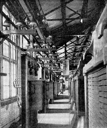
The joints are spliced and wrapped, but are not soldered. An interesting difference in the behavior of the old and new lines when the wind is blowing at high velocity has been observed. At such times, the tightly strung copper conductors of the old line swing or vibrate irregularly, but on the whole rapidly, and the strain caused by this vibration is transmitted to the insulators, pins, cross arms and poles in such a manner that the trembling of the pole may be detected by placing the hand against it at a point near the ground. Under similar circumstances, the aluminum conductors tend to assume a fixed position, which is sometimes apparently as much as 45 degrees from the vertical plane in which they hang when the air is quiet. There is practically no vibration perceptible at the pole. The elimination of vibrating strains upon insulator and pin is gratifying, as in the old line the tendency of insulators to work loose from their pins has been noticeable and I have no doubt that it has been caused by the vibration of the conductors during heavy wind storms. In connection with the construction of the new line the high potential connections of the step-up transformer house were radically changed by all these connections being brought up from an air chamber beneath the transformers, in which they had been placed originally, and supported upon "Type C" insulators carried by a frame work of hard wood and angle iron, as illustrated in Fig. 28.
| |||
| Fig. 28. |
Present Output of the Plant.In Fig. 29 the load curve for local service and for long distance service, as compiled from half hourly wattmeter readings for the twenty-four hours ending at midnight July 20, 1901, is shown. The local load varies between 14,200 K. w. and 15,700 K. w. This remarkable uniformity of output is explained by the fact that nearly all of the power used
[not finished]
